The Who What When Where Why
Open Research Institute is a non-profit dedicated to open source digital radio work on the amateur bands. We do both technical and regulatory work. Our designs are intended for both space and terrestrial deployment. We’re all volunteer and we work to use and protect the amateur radio bands.
You can get involved in our work by visiting https://openresearch.institute/getting-started
Membership is free. All work is published to the general public at no cost. Our work can be reviewed and designs downloaded at https://github.com/OpenResearchInstitute
We equally value ethical behavior and over-the-air demonstrations of innovative and relevant open source solutions. We offer remotely accessible lab benches for microwave band radio hardware and software development. We host meetups and events at least once a week. Members come from around the world.
Solution to July Puzzle
August Puzzle: The Mysterious Lock Loss
— SCENARIO: You’re debugging a Costas loop implementation that works
— perfectly in simulation but fails intermittently in hardware.
— The loop locks quickly to F1 (carrier + 1kHz), but when the
— input switches to F2 (carrier + 3kHz), it sometimes loses lock
— entirely instead of reacquiring.
—
— PUZZLE: What’s causing this intermittent lock loss?
— HINT: Look carefully at the loop filter characteristics and gain scheduling.
library IEEE;
use IEEE.STD_LOGIC_1164.ALL;
use IEEE.NUMERIC_STD.ALL;
use IEEE.MATH_REAL.ALL;
entity costas_loop_puzzle is
generic (
DATA_WIDTH : integer := 16;
PHASE_WIDTH : integer := 12;
F1_OFFSET : integer := 1000; — 1 kHz offset from carrier
F2_OFFSET : integer := 3000 — 3 kHz offset from carrier
);
port (
clk : in std_logic;
reset : in std_logic;
rf_input : in signed(DATA_WIDTH-1 downto 0);
freq_select : in std_logic; — ‘0’ for F1, ‘1’ for F2
— Outputs for debugging
i_data : out signed(DATA_WIDTH-1 downto 0);
q_data : out signed(DATA_WIDTH-1 downto 0);
phase_error : out signed(DATA_WIDTH-1 downto 0);
vco_freq : out signed(PHASE_WIDTH-1 downto 0);
lock_detect : out std_logic
);
end entity;
architecture behavioral of costas_loop_puzzle is
— VCO signals
signal vco_phase : signed(PHASE_WIDTH-1 downto 0) := (others => ‘0’);
signal vco_i, vco_q : signed(DATA_WIDTH-1 downto 0);
signal vco_control : signed(DATA_WIDTH-1 downto 0) := (others => ‘0’);
— Mixer outputs
signal mixer_i, mixer_q : signed(DATA_WIDTH-1 downto 0);
— Loop filter components
signal integrator : signed(DATA_WIDTH+4-1 downto 0) := (others => ‘0’);
signal proportional : signed(DATA_WIDTH-1 downto 0);
signal error_signal : signed(DATA_WIDTH-1 downto 0);
— Lock detection
signal error_magnitude : unsigned(DATA_WIDTH-1 downto 0);
signal lock_counter : unsigned(15 downto 0) := (others => ‘0’);
— Critical parameters (this is where the puzzle lies!)
constant KP : signed(7 downto 0) := to_signed(32, 8); — Proportional gain
constant KI : signed(7 downto 0) := to_signed(2, 8); — Integral gain
— Gain scheduling based on frequency (THE TRAP!)
signal adaptive_kp : signed(7 downto 0);
signal adaptive_ki : signed(7 downto 0);
begin
— Gain scheduling logic – reduces gains at higher frequencies
— This looks reasonable but creates the error starvation!
process(freq_select)
begin
if freq_select = ‘0’ then — F1 mode
adaptive_kp <= KP;
adaptive_ki <= KI;
else — F2 mode – “optimize” for stability at higher frequency
adaptive_kp <= shift_right(KP, 2); — KP/4
adaptive_ki <= shift_right(KI, 3); — KI/8
end if;
end process;
— VCO phase accumulator
process(clk, reset)
begin
if reset = ‘1’ then
vco_phase <= (others => ‘0’);
elsif rising_edge(clk) then
vco_phase <= vco_phase + vco_control;
end if;
end process;
— VCO sine/cosine generation (simplified)
— In real implementation, this would be a lookup table
vco_i <= to_signed(integer(32767.0 * cos(real(to_integer(vco_phase)) * MATH_PI / 2048.0)), DATA_WIDTH);
vco_q <= to_signed(integer(32767.0 * sin(real(to_integer(vco_phase)) * MATH_PI / 2048.0)), DATA_WIDTH);
— Quadrature mixers
process(clk)
begin
if rising_edge(clk) then
— Multiply and low-pass filter (simplified)
mixer_i <= shift_right(rf_input * vco_i, 15);
mixer_q <= shift_right(rf_input * vco_q, 15);
end if;
end process;
— Costas loop error detector (classic I*sign(Q) approach)
process(clk)
variable q_sign : signed(DATA_WIDTH-1 downto 0);
begin
if rising_edge(clk) then
if mixer_q >= 0 then
q_sign := to_signed(1, DATA_WIDTH);
else
q_sign := to_signed(-1, DATA_WIDTH);
end if;
error_signal <= shift_right(mixer_i * q_sign, 8);
end if;
end process;
— Loop filter with adaptive gains
process(clk, reset)
variable scaled_error : signed(DATA_WIDTH+4-1 downto 0);
variable prop_term : signed(DATA_WIDTH+4-1 downto 0);
begin
if reset = ‘1’ then
integrator <= (others => ‘0’);
vco_control <= (others => ‘0’);
elsif rising_edge(clk) then
— Scale error by adaptive gains
scaled_error := resize(error_signal * adaptive_ki, DATA_WIDTH+4);
prop_term := resize(error_signal * adaptive_kp, DATA_WIDTH+4);
— Integrate with adaptive gain
integrator <= integrator + scaled_error;
— PI controller output
vco_control <= resize(shift_right(integrator + prop_term, 4), DATA_WIDTH);
end if;
end process;
— Lock detector – measures error magnitude
process(clk, reset)
begin
if reset = ‘1’ then
lock_counter <= (others => ‘0’);
lock_detect <= ‘0’;
elsif rising_edge(clk) then
error_magnitude <= unsigned(abs(error_signal));
if error_magnitude < 100 then — Low error threshold
if lock_counter < 65535 then
lock_counter <= lock_counter + 1;
end if;
else
lock_counter <= (others => ‘0’);
end if;
— Declare lock after 1000 consecutive low-error samples
if lock_counter > 1000 then
lock_detect <= ‘1’;
else
lock_detect <= ‘0’;
end if;
end if;
end process;
— Output assignments
i_data <= mixer_i;
q_data <= mixer_q;
phase_error <= error_signal;
vco_freq <= resize(vco_control, PHASE_WIDTH);
end behavioral;
Defending Amateur Radio Spectrum: The AST SpaceMobile Battle Continues
Partial Victory in 430-440 MHz Band Defense
The amateur radio community has achieved a significant but limited victory in protecting the 430-440 MHz band from commercial satellite encroachment. AST SpaceMobile’s request for broad commercial use of amateur spectrum has been restricted to emergency-only operations for a maximum of 24 hours and only 20 satellites—but the fight isn’t over.
AST SpaceMobile (AST & Science LLC) operates a constellation of large commercial satellites designed to provide cellular service directly to mobile phones. Think of it as trying to turn satellites into massive cell towers in space. The problem? They wanted to use the 430-440 MHz amateur radio band for their Telemetry, Tracking, and Command (TT&C) operations across a planned 243-satellite constellation.
This isn’t just about frequency coordination—it’s about fundamental spectrum philosophy. The amateur bands exist for experimentation, emergency communications, and education. Commercial operations fundamentally change the character of these allocations, much like turning a public research laboratory into a private factory floor.
The Technical Challenge
AST SpaceMobile’s satellites are massive. These are some of the largest commercial satellites ever deployed, with solar arrays spanning over 700 square meters. These aren’t small CubeSats doing modest experiments. They are industrial-scale infrastructure requiring robust command and control systems.
The company initially deployed five Bluebird satellites in September 2024, operating on amateur frequencies at 430.5, 432.3, 434.1, 435.9, and 439.5 MHz with 50 kHz bandwidth. These were launched and operated without proper authorization. Each planned satellite would require TT&C channels with bandwidths between 64 – 256 kHz, creating a significant interference footprint across the entire 10 MHz amateur allocation.
The Open Research Institute, along with numerous international amateur radio organizations, filed strong opposition to AST SpaceMobile’s request. Our argument was both technical and philosophical:
Summarized from our filed comment, the technical objections included the following.
1) Multiple established commercial satellite bands exist (S-band: 2025-2110 MHz, X-band: 8025-8400 MHz, Ka-band: 27.5-30.0 GHz)
2) ITU studies specifically excluded the 430-440 MHz amateur allocation from commercial TT&C considerations
3) Modern satellite technology readily supports operations in higher frequency bands with better propagation characteristics. 430-440 MHz is not the best choice.
We raise the following philosophical and cultural concerns.
1) Amateur radio bands serve critical emergency communications when commercial infrastructure fails
2) These frequencies support STEM education and technological innovation. Where do you think many RF engineers get their start?
3) Commercial encroachment sets a dangerous precedent that could completely destroy the experimental character of amateur allocations
The FCC’s Decision: A Limited Victory
On August 29, 2025, the FCC issued a modified grant that significantly restricts AST SpaceMobile’s operations:
1) 24-hour limit. TT&C operations in the 430-440 MHz band are permitted only for periods not exceeding 24 hours.
2. Emergency only. Operations are restricted to Launch and Early Orbit Phase (LEOP) and emergency situations when no other band is available.
3. 20-satellite cap: Authorization covers only the next 20 satellites, including the FM1 prototype.
FM1 stands for “Flight Model 1” and is AST SpaceMobile’s first “Block 2” BlueBird satellite. It’s a much bigger, more powerful version of their current satellites. According to AST, it is about three times larger than their first-generation BlueBird satellites with 10 times the capacity. Launch dates have been delayed over the past year and the satellite might go up in early 2026.
This represents a major step back from AST SpaceMobile’s original request for blanket commercial access across their entire constellation.
What Does This Mean for the Amateur Community?
The decision validates several key principles that we and many others have been patiently asserting to regulators.
1) Amateur spectrum is different. The FCC acknowledged that amateur allocations can’t simply be treated as general-purpose commercial spectrum. The severe restrictions imposed recognize the unique character and public service value of amateur radio.
2) Technical alternatives exist. By limiting operations to emergencies “when no other band is available,” the FCC effectively endorsed our argument that commercial TT&C bands are technically viable for these operations.
3) Precedent matters. While it shouldn’t have to be repeatedly argued, precedent really does matter and vigilance is required in order to keep a solid regulatory foundation for amateur radio. Rather than opening the floodgates to commercial use of amateur spectrum, the FCC imposed strict limits that discourage similar requests from other operators.
Industry Response and Next Steps
AMSAT-DL described this as a “greater (partial) success” for amateur radio and AMSAT satellite operators. The 24-hour emergency-only restriction and 20-satellite cap should give AST SpaceMobile sufficient time to redesign their constellation for proper commercial frequency usage.
However, this isn’t a complete victory. AST SpaceMobile still has temporary access to amateur spectrum, and the company may seek to extend or modify these restrictions as their constellation develops.
Lessons for Open Source and Amateur Communities
This case illustrates several important principles for defending community resources. Documentation matters. Technical arguments backed by ITU studies, engineering analysis, and regulatory precedent carried significant weight in the FCC’s decision. Without this, things would have worked out very differently.
Community coordination works. International amateur radio organizations presenting unified opposition demonstrated the global impact of spectrum decisions.
Vigilance must continue. Protecting community resources, whether spectrum, software licenses, IP addresses, or technical standards, requires continuous engagement with regulatory and governance processes.
The amateur radio community must remain vigilant as commercial space operations continue expanding. AST SpaceMobile’s modified authorization creates a framework for emergency use that other operators will definitely seek to exploit.
We encourage continued support for organizations like AMSAT-DL, ARRL, and the Open Research Institute that actively defend amateur spectrum rights.
You can participating in FCC comment periods on spectrum issues. Yes! You! Reach out to your local amateur radio organization and be part of the process. Support technical education that demonstrates amateur radio’s ongoing innovation. Engage with emergency communications activities that highlight amateur radio’s public service value.
The 430-440 MHz band remains primarily protected for amateur use, but this victory required sustained technical and legal advocacy. Our spectrum allocations, just like our open source projects, exist because communities actively defend and develop them. The technical part of a project is never the hardest part. The hardest part of any project is the people part. Negotiating, collaborating, compromising, defending, and communicating in a complex world are all “people work”.
Technical Details and References
For those interested in the regulatory details, please refer to the following documents.
FCC Proceeding 25-201 (application/licensing proceeding)
ICFS File Number SAT-MOD-20250612-00145 (FCC’s “case number” or filing reference for AST SpaceMobile’s request to modify their satellite authorization.)
Open Research Institute Comment to 25-201 (Filed July 21, 2025 by Michelle Thompson W5NYV)
FCC Decision (DA-24-756A1.pdf from August 29, 2025)
The full technical analysis includes frequency coordination studies, interference modeling, and alternative band analysis available through the FCC’s Electronic Comment Filing System.
ORI’s Tiny Payload Delivered to AmbaSat
Most recent mission update from AmbaSat is below.
Dear AmbaSat Launch Partner,
A big thank you to everyone who has already returned their AmbaSat-1 ChipSats – your support and timely action are helping to keep us on track for mission integration.
If you haven’t yet returned your ChipSat, we kindly ask that you do so as soon as possible to ensure its inclusion in the upcoming 3U CubeSat assembly. If there are any issues or delays, please don’t hesitate to contact us directly at support@ambasat.com — we’re happy to assist.
Mission Update
We’re pleased to share that the UK Civil Aviation Authority (CAA) engineering team recently visited AmbaSat HQ, where they carried out a detailed review of our processes, concept of operations, risk management strategy, and supporting documentation. Twice-monthly CAA meeting are ongoing and:
Following the visit, we’ve developed a focused CubeSat action plan to:
Reduce the risk of fragmentation from stored energy
Strengthen documentation of our engineering methodology and V&V campaign
Document and minimise the chance of accidental debris release
Finalise details of the ground segment and operational architecture, including responsibilities and procedures
Document acceptable re-entry and collision risks
Produce additional virtual modelling of the combined AmbaSat, Flight Tray, and CubeSat assembly
In summary, we’re making solid progress towards both integration and licensing milestones, and we’ll continue to keep you updated as the mission advances.
Thank you once again for being part of this exciting step into Low Earth Orbit.
Ad Astra,
Martin & the AmbaSat Team
AmbaSat Ltd
Office: +44 (0)1609 600884
Email: martin@ambasat.com
Web: https://ambasat.com
Opulent Voice Progress Report: Issue #22
Paul Williamson, KB5MU
Here’s a summary of Dialogus debugging progress leading up to September 2, 2025 and resulting in improved code committed to Git at https://github.com/OpenResearchInstitute/dialogus/commit/741137a17cadbf68086392bce4805cf1d037a029 . The problems we were attempting to address, and some of the key observations made along the way, are captured in this Git issue: https://github.com/OpenResearchInstitute/dialogus/issues/22
Recall that the problems we were seeing had to do with the flow of encapsulated Opulent Voice frame data to be transmitted from the user interface program Interlocutor to the transmit output of the Pluto, where we can observe it with the Rigol RSA5065N spectrum analyzer in the Remote Lab. Let’s start with a rundown of the components of that flow, as implemented here in the lab.
Components of the Frame Data Flow for Transmit
Interlocutor (https://github.com/openresearchinstitute/interlocutor) is a Python program running on a Raspberry Pi 5. It accepts voice input from an attached microphone and/or text message input from a keyboard. Interlocutor understands the logical structure of an over-the-air Opulent Voice frame. It composes these frames to contain the data to be transmitted. Each frame contains 12 bytes of Opulent Voice frame header and 122 bytes of COBS-encoded payload data, for a total of 134 bytes.
Interlocutor encapsulates each packet into a UDP message with port number 57372 addressed to the IP address of the Pluto. The Linux networking stack routes this by IP address to the appropriate network interface port, eth1 in this case.
But eth1 is not physically an Ethernet port at all. The Pluto doesn’t have an Ethernet port. It does have a USB port, and one of the standard ways to connect a Pluto to a computer is to use Ethernet over USB. There are several such protocols, any of which can make the USB connection act like a network connection. The supported protocols on the Pluto are RNDIS, CDC-NCM, and CDC-ECM. Linux supports all three of these protocols, but Windows and macOS each support only one, and of course it’s not the same one. Because we are using more Macs than Windows computers here, we chose CDC-NCM, which is the one supported by macOS. This is configured in the Pluto as explained in https://wiki.analog.com/university/tools/pluto/users/customizing
So our encapsulated packets flow over this simulated Ethernet and arrive in the Pluto. Recall that the Pluto is based on a Xilinx device that contains an ARM computer core and an FPGA fabric (Zynq XD7Z010-1CLG225C), plus an Analog Devices AD9363 radio transceiver. The ARM core runs a build of Linux provided by Analog Devices at https://github.com/analogdevicesinc/plutosdr-fw , which we have lightly customized at https://github.com/openresearchinstitute/pluto_msk/firmware . The encapsulated packets arrive over the USB port (which is part of the Zynq) and are handled by the Linux network stack running on the ARM.
Dialogus (https://github.com/openresearchinstitute/dialogus) is a C program running under Linux on the Pluto’s ARM. Built with the command line flag -DOVP_FRAME_MODE, it listens for the encapsulated Opulent Voice frames arriving on UDP port 57372. Its job is to arrange for the frames to be transmitted in the specified way using the MSK modulator.
The MSK modulator is a part of Locutus (https://github.com/openresearchinstitute/pluto_msk), the FPGA-based implementation of an Opulent Voice modem. Overall, Locutus is a modification of the standard reference design for the Pluto FPGA, provided by Analog Devices within https://github.com/analogdevicesinc/hdl . The reference design is what ships installed with the Pluto to create the PlutoSDR product. PlutoSDR is what’s usually described as a Software Defined Radio (SDR) device. That is, it is a translator between I/Q samples and RF signals, capable of any type of radio transmission and/or reception within its limits of frequency coverage, bandwidth, and sample rate, but only in conjunction with a computer that can supply and/or interpret the stream of I/Q samples. The device itself doesn’t know anything about any modulation or waveform details. That’s up to the connected computer.
Since the goal was to implement the modem inside the FPGA, we add modem blocks inside the mostly-unchanged FPGA reference design. Instead of exchanging I/Q samples with the computer, it exchanges data bits.
Inside the reference design, data flow between blocks is mostly done using a scheme called AXI-S (Advanced eXtensible Interface – Stream). This involves multiple handshaking signals between any two communicating blocks, arranged such that a small quantum of data is transferred when both sides are ready for the transfer, no sooner and no later. Each block has to be designed so that it can pause its operation seamlessly and await the readiness of the other block. This scheme allows for various blocks within the design to process at different speeds, even varying their processing rate in time, without any block falling behind.
Specifically, in the transmit pipeline, the first major block that handles incoming data from the computer is a specialized DMA controller, with access to the ARM’s memory on the computer side and an AXI-S interface on the other side. In the reference design, this DMA controller feeds into a series of scaling and filtering facilities, which in turn feed into the final processing stages before the DACs. We replaced the unneeded scaling and filtering blocks with the MSK modulator block. Data bits come in from the computer’s memory through the DMA controller and are delivered to the input of the Modulator block. The Modulator block outputs I/Q samples, which pass on into the rest of the reference design’s pipeline, eventually to be delivered to the DACs to create the analog signals.
The framework that controls how a computer talks to and controls PlutoSDR is called IIO, for Industrial Input/Output. It’s an extensive system meant to be general purpose for all sorts of devices that stream data to and/or from a computer, fast or slow. Besides the sample streams themselves, IIO provides a variety of control and status functions. With these, the computer can control the radio as well as the flow of samples. The computer side of IIO can be run on a local machine such as the ARM inside the Pluto, or over a USB interface, or over a network interface. So, PlutoSDR with IIO is __almost__ exactly what we needed. We use IIO essentially as in the reference design, except that we abuse the IIO interface with the computer by using it to carry data bits instead of I/Q samples.
One other thing that will turn out to be important about IIO: because it’s designed to work with both fast hardware and relatively slow software, it handles samples in relatively large batches. The user software creating transmit samples fills up a buffer full of samples using IIO utility functions, and then “pushes” that buffer into the Linux kernel where the actual transfer takes place. The kernel manages a finite pool of buffers, four by default, though this can be adjusted. If a kernel buffer is available, the push operation is quick. If the kernel buffers are all in use, presumably three are full and waiting their turn and one is actively being transferred to the hardware. In that case, an attempt to push a new buffer will result in the user program blocking until a kernel buffer is freed. This creates a similar effect to the AXI-S handshaking: the user program is slowed down so it never gets too far ahead of the hardware processing.
The 8X Problem
The problem initially detailed in Issue #22 referenced above was that the transmission observed on the spectrum analyzer was taking approximately eight times as long as it should have been taking. The shortest transmission is a single 40ms frame, but we also send a 40ms frame of preamble before the data frame, and follow it with 25 dummy frames (one second) of “hang time” in case another transmission comes along right away, and follow that with a 40ms frame of postamble. So that short transmission occupies 28 frames, which is 1120ms at 40ms per frame. The duration actually observed was estimated at 8500ms using a stopwatch. Here’s what it looked like on the waterfall on the spectrum analyzer.
Image: Short transmission extended by 8x
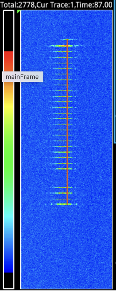
The Zynq contains a hardware clock that’s useful for precise timestamping from software. I made use of this facility to timestamp each frame, and found most of them to be spaced 302ms to 303ms apart, instead of the nominal 40ms. The spacing was suspiciously consistent. What’s more, the first few frames were transferred more quickly. This was consistent with the spectrum analyzer waterfall display shown in the original issue #22 comment.
After some confusion and fiddling around, the cause became evident. The IIO buffer size in use had not been adjusted to match the size of the transfer. It was set to 1024 samples. Since the Opulent Voice system is intended to be used with realtime voice conversations, we don’t buffer up multiple frames. Instead, there’s an IIO transfer for each individual frame. Since we are sending the logical data from the UDP-encapsulated frame, that is only 134 bytes. 1024 / 134 = 7.6, and 7.6 * 1120ms is 8559ms, neatly accounting for the observed duration. The software was packing 134 bytes into each buffer, and then pushing the whole 1024-byte buffer into the kernel, and the Pluto had no way to know that only the first 134 bytes were significant.
There are two ways to solve that. The simplest way is to change the buffer size to match the frame size, 134. With no other changes, that eliminated almost all of the excess delay. The other way is to leave the buffers alone, and instead replace the calls to iio_buffer_push() with calls to iio_buffer_push_partial() and pass a length of 134 to the latter function. We were suspicious of iio_buffer_push_partial(), because we remembered having difficulty with it in a previous encounter, so I tried both methods and compared the results. Both apparently worked the same. I decided to stick with changing the buffer size to 134.
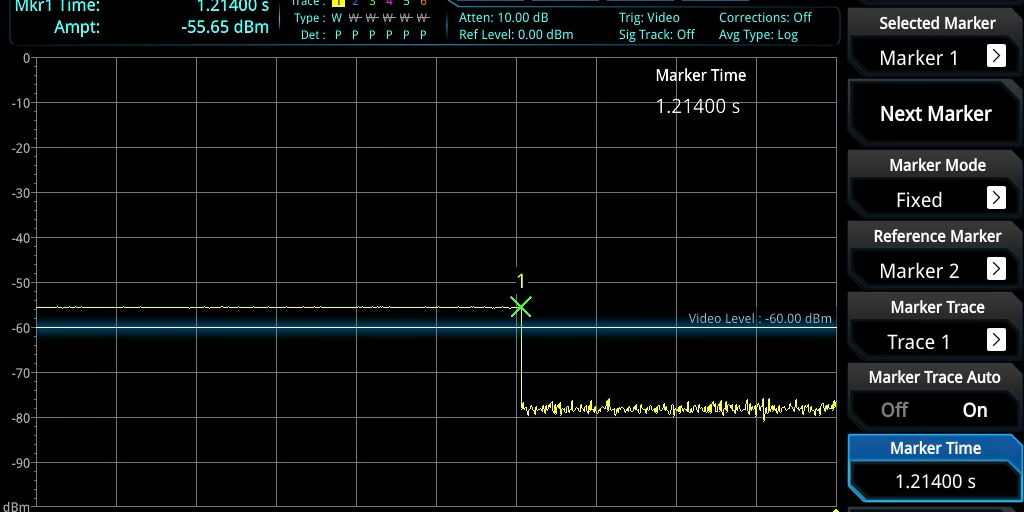
Looking again at the waterfall display on the spectrum analyzer, we could see that the duration was very close to correct, even though there’s no way to get a precise time measurement from the waterfall display. But now we had precise timestamps in the code, and we could see from the timestamps that the duration was still a little bit long, 1214ms instead of 1120ms. That was an extra 94ms unaccounted for. I re-learned how to use the spectrum analyzer in zero-span mode, and was able to see that the 1214ms duration was real, and not an error in how the timestamps were handled.
Image: 4ms transmission seen in zero-span mode
Putting the spectrum analyzer back into waterfall mode, we observed that the signal was not entirely clean during that 1214ms period. There appeared to be small gaps in the modulation. Something was still wrong.
Possibly Leaking Kernel Buffers
The timestamp trace (posted in a comment to Issue #22) showed that each call to iio_buffer_push() was taking about 39ms to return. That was nice and consistent, but it should not have been. With four kernel buffers allocated, at least the first three calls to iio_buffer_push() ought to return very quickly. But we weren’t seeing that, even after long idle periods.
A reboot of the Pluto cleared up this issue. We found that all 28 of the iio_buffer_push() calls in a short transmission were returning in under 2ms, as expected. The overall duration of the transmission had fallen to 1135ms, just 15ms longer than nominal.
This was still a little too long to attribute to measurement uncertainty. We concluded that there were probably brief underruns adding delays between frames, and attributed this to a timeline with no slack for timing uncertainty introduced by the USB Ethernet interface. We resolved to get control over the timeline and redesign it with wider windows, but in the meantime we moved on to longer transmissions. Voice transmissions.
Voice Transmissions Still Getting Stretched
We made voice transmissions for a count of 10 or 20 mississippis using the PTT button in the Interlocutor GUI. During the transmission, we observed the waterfall display on the spectrum analyzer. There appeared to be tiny gaps, medium sized gaps, and a few pretty large gaps in the modulation (never in the overall power). That’s not right.
We were also collecting timestamp information, of course. It showed that there were 469 encapsulated frames processed, which would add up to 18.76 seconds at 40ms each. At this point, we happened to be using iio_buffer_push_partial(), and the debug log showed 645 calls to iio_buffer_push_partial(). The 645 – 469 = 176 extra pushes could only have been frames inserted by the Dialogus code. It always inserts a preamble frame and a postamble frame, and the log showed that it inserted 174 dummy frames, so that adds up. Only the 25 dummy frames at the end of the transmission are expected, leaving 149 dummy frames that must have been inserted due to underruns. That is, when a 40ms boundary passes and no new encapsulated frame data is available, Dialogus sees this as a possible end of the transmission and starts to count off a one-second hang time filled with dummy frames. This event was also visible in the log, 61 times. That works out to about 2.5 dummy frames emitted per declared hang time. That’s too much to be due to narrow timing windows; each failure to hit a window by a millisecond or several would only generate a single dummy frame. There were still excess dummy frames being sent.
I made a table of the function call durations for iio_buffer_push_partial(), which we were still using at that time. It tells a confusing story. A total of 18 calls were 7ms or less, indicating that the kernel buffer was freed around the same time the next buffer was pushed. A total of 501 calls were clustered around 40ms, indicating that all the kernel buffers were full around the time the next buffer was pushed. The remaining 126 calls had durations ranging all the way up to 1000ms, which caused an IIO timeout error. How is that possible, with only four kernel buffers that only take 40ms each to clear out? Seemingly at least one of these assumptions is wrong.
A Period of Confusion
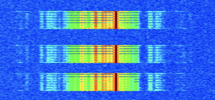
We went back to trying to characterize the behavior during short transmissions, mainly because they seemed a lot closer to being correct and they were easier to experiment with. I captured a test with three short transmissions on the waterfall, with matching log files. The three transmissions contained exactly the same data, but they did not look alike on the waterfall. The visible gaps looked different.
We mused about the limitations of the waterfall display. It works by capturing some number of samples, doing an FFT on them, and drawing a row of pixels on the display, and that happens approximately 30 times per second. I don’t recall seeing any documentation on how many samples are used, but it’s probably much less than 100% duty cycle. Worse, 30 per second is barely faster than our frame rate of 25 per second, so we are unlikely to clearly see any details at the level of individual frames, much less fractions of a frame. A faster waterfall display would be useful to have.
For these three short transmissions, I measured the time between successive calls to iio_buffer_push(). Except for several well-understood special cases, they were all clustered tightly around 40ms, as expected.
Image: Three short transmissions on the waterfall
I also measured the duration of each iio_buffer_push() call. They were all 1ms or shorter. That’s good.
And the overall transmission session durations were 1132ms, 1134ms, and 1133ms, still a tiny bit long. Maybe that could be explained as overhead?
The only worrisome indication of a problem was the appearance of the waterfall, and we’re not sure how meaningful that really is for these short transmissions. But we hadn’t forgotten the voice tranmissions, which were clearly terrible on the waterfall.
USB Ethernet Suspected
I had spent a lot of energy trying to blame the USB Ethernet connection between the Raspberry Pi and the Pluto. Probably because it was an external interface that I didn’t fully understand and could not trace. I went so far as to shop for USB sniffer devices so we could see what was actually happening on the bus. They are expensive, and none of the devices I found advertised a feature for tracing USB Ethernet.
To try and answer this question, I made a special Dialogus build that didn’t process any of the encapsulated frames beyond noting their length and some bytes of data from each one. This removed any interaction with the FPGA from the test scenario. I ran a lengthy transmission through it. Every single encapsulated frames arrived like clockwork, within several milliseconds of 40ms. The USB Ethernet was working fine when isolated from IIO.
Doing the Arithmetic
During Open Research Institute’s regular Tuesday morning Zoom call for FPGA development projects and such, we had a chance to discuss this with the designer of Locutus, Matthew Wishek, NB0X (see https://www.openresearch.institute/2025/08/04/matthew-wishek-wins-2025-arrl-technical-innovation-award/ ). I had made an attempt to read the relevant VHDL code in the pluto_msk repository to clarify my understanding of how the Modulator interacted with the surrounding AXI-S interfaces. Matthew confirmed my shaky understanding that the Modulator would consume data bits at an absolutely constant rate, and that it was not capable of slowing down for an underrun or of exerting extra “backpressure” on a data source that was trying to go too fast. That constant rate was familiar to me from working on the numerology for the older 4FSK version of Opulent Voice: 54200 bits per second.
A bit of light began to dawn.
That number is based on a full implementation of the Opulent Voice waveform. It starts from our choice of one of the recommended bit rates for the Opus audio codec, which is the key to excellent voice quality. We long ago decided to allow the voice codec to use 16000 bits per second. We also chose one of the frame durations recommended by Opus, 40ms. 16000 * 0.040 = 640 bits = 80 bytes. Wrap it up in IP/UDP/RTP as is usually done for streaming Opus on networks, and you’re up to 80 + 12 + 8 + 20 = 120 bytes. Add 2 for packet framing using COBS, 122. Add 12 bytes of frame header consisting of 6 bytes of station ID, 3 bytes of authentication tag, and 3 bytes reserved for protocol use, and that’s where the 134 byte 40ms frame comes from.
But that’s not the end of the transmitting process. The header is Golay encoded for FEC, which doubles it size to 24 bytes. The COBS data (including IP/UDP/RTP/Opus) is convolutionally encoded for FEC, which doubles its size as well. Now we’re up to 268 bytes. We also prepend an uncoded frame synchronization word before each frame, so the receiving modem can unambiguously find the frame boundaries. The frame sync is 3 bytes long, so now it’s 271 bytes, 2168 bits, and THAT is what gets fed to the MSK Modulator.
2168 bits * 25 frames/second = 54200 bits per second.
We had been sending the raw data, 134 bytes per frame, to Locutus. That would be great if Locutus implemented the FEC codes and prepended the frame sync word. However, at the current state of development, Locutus is just a bare Modulator. It takes a stream of bits, which have to be at 54200 bits per second, and modulates them using MSK, and that’s all it does. The software doesn’t implement those features, either. We haven’t even reached a firm decision about where those features *should* be implemented, hardware or software. So it was never going to work like that, and we knew that from the start.
I got to work modifying the Dialogus code to send frames of the right length. I added calls in the frame building logic to encode the header and the payload for FEC, and wrote dummy routines that fake the FEC codes by simply including the contents twice. I changed the buffer size to 271, and added checks to make sure the built frames were 271 bytes long. This would at least come close to keeping the Modulator well-fed.
Close But No Cigar
Actually, when tested, it was worse. A lot worse. Nearly every call to iio_buffer_push() was taking a long time. I now understood this to mean that the Modulator was consuming data more slowly than we were trying to send it. Not only were the kernel buffers all full, but they were taking a lot more than 40ms each to empty out.
Nonetheless, I was baffled. I re-examined the code that filled up the buffers, for probably the seventeenth time. This is some of the oldest code in the program, having been taken originally from the Analog Devices example code for streaming samples to a PlutoSDR. It’s full of cryptic calls to IIO utility routines, but I knew what those routines did, and it was nothing very complicated in this case where we had only one I/Q channel open for transmit. Really they were just setting up start index, end index, and stride for a loop that would visit each sample in the buffer. One sample for every channel (total of one channel) would constitute an AXI-S transfer when it got into the FPGA, and that same increment was the unit for allocating buffer sizes. Each sample had room for 16 bits of I and 16 bits of Q. Four bytes. Of course, I knew I had to put one byte of frame data in there instead of I/Q samples, and that’s what the code was doing.
There was one weird thing about the code that I did not know the story behind. The code put that one byte of data in two places within the I/Q sample. It carefully copied the data byte into the high byte of the I and then copied it again into the low byte of the Q. There were lovely comments on each line describing accurately what each line of code was doing at the byte level. Whoever wrote that code must have known the reason for it. Maybe they figured that by filling in the first byte and the last byte, they’d have a good chance of having the byte in the right place. Clearly they were aware that only one data byte needed to go into the sample. Unless they were an LLM.
Funny story. I knew for sure that those lines of code had been changed from the Analog Devices reference code. I remembered that the transmit buffers in that reference code had been filled with all zeroes. Which is just about the stupidest thing you could put into the I/Q samples of a demonstration intended to show how it worked. It would generate no modulation for most normal modulation types, and no power output at all for amplitude-modulation methods. Which we learned the hard way, and wasted some time tracking down.
Anyway, despite several good reasons I should have known better, I assumed that code was probably right and went looking for other things to check.
What About the Register Initializations?
There are a bunch of reads and writes to registers in Locutus as part of the initialization code in the main() function of Dialogus. These were inherited from older programs that did their jobs successfully. Some had been modified as new registers were added, mostly to help with debugging. I undertook to read and check them all against the register definitions. I wasn’t really expecting to find anything.
Until I got to the TX_DATA_WIDTH register. Short description, “Modem Tx Input Data Width”. Long description, “Set the parallel data width of the parallel-to-serial converter”. Default value at reset: 8. I knew what this was. The Modulator block is designed to be flexible about its input format, to make it easier to connect to a variety of hosts. When an AXI-S transfer arrives at the Modulator, this register tells it how many bits of that transfer contain meaningful data bits for modulation. I knew it was 8. It had to be 8, because we needed to send an odd number of bytes in each transfer.
But it wasn’t set to 8 in the initialization code. It was set to 32. That meant the Modulator was trying to send out four bytes for every one byte that we intended. I changed it to 8.
I also wanted to know where in the 32-bit “sample” the 8-bit data was supposed to go. I ran a sequence of tests at TX_DATA_WIDTHs of 8, 16, and 24, checking for modulation with data in each of the four locations within the sample. It turns out the buffer-filling code was wrong in both of the positions where it placed the data byte. It should have been placed in the lower byte of I. This is now corrected and documented in the code.
Characterizing the Results
I made a long voice transmission with all the usual logging. The waterfall looked good, no dropouts visible. The higher tone was much stronger than the lower tone, but that could be just because the data wasn’t scrambled for whitening or really encoded.
I extracted some statistics from the log file and did what felt like a systematic and thorough evaluation. Everything looked good and I got excited and committed the fixed code. I didn’t say so online, but I thought it was fixed. I did promise a detailed report “later on”, and that turned into this document.
On further study (as a result of writing this document) I can see that there are definitely still some things wrong, and clues about where to look next.
The elapsed time between calls to iio_buffer_push() was a mix of around 40ms (2736 occurrences) and around 0ms (662 occurrences). There were no outliers or long waits between push calls. I’m not sure I understand the mix of 40ms and 0ms elapsed times, but I suspect it can be explained by timing jitter around a too-narrow window. Some more debugging may be needed on this one.
I measured the duration of every iio_buffer_push() call. They were all quick. Most values were 0ms, none were longer than 2ms, and only a few examples of 2ms in the run. This is what I’d hope to see.
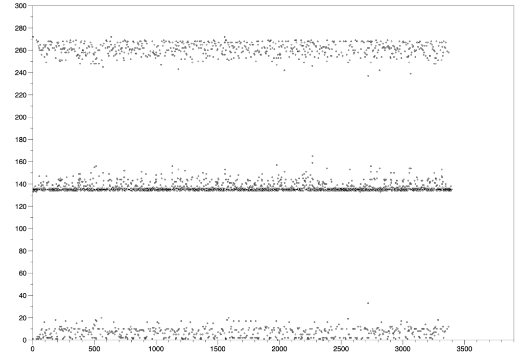
I also looked at the axis_xfer_count register. This is one I haven’t mentioned before. It is supposed to measure how many AXI-S transfers have taken place. I logged it as a cumulative value and also as a differential between pushes. The difference between start of session and end of session was 458597 transfers, which is almost exactly 135 (not 134) transfers per push, but 169.4 transfers per frame as measured by the overall duration of the session, which was 2707 x 40ms. Neither of those numbers makes sense. It ought to be 271 per frame now. The distribution of the delta values was interesting, too.
I logged starts and cancels of hang times. There were 664 hang times declared and canceled. I didn’t log dummy frames, but I captured periodic statistics reports and they reveal that 689 dummy frames were sent. Discarding the 25 dummy frames at the natural end of transmission, that’s 664 dummy frames, exactly one for each hang time declared. That’s what we would expect from short underruns. Looking for patterns in the hang time events, I see cases where an encapsulated frame is logged as arriving after a hang time is declared, but the hang time is not canceled. This suggests race conditions in the hang time checking.
Image: Delta of axis_xfer_count between buffer pushes
Conclusion
The debugging detailed here was (probably) good progress, but there’s more work to do before we can consider the problems solved.
The final test will of course be to receive the transmissions created this way, and check that the data error rate is appropriate at a variety of signal strengths. Getting the receiver to work that well may be the harder part of the problem, so it’s essential to keep looking at Dialogus until every weird behavior is understood or corrected.
IIO Timeline Management in Dialogus — Transmit
Paul Williamson, KB5MU
The next step in debugging/optimizing the design of the transmit pipeline in Dialogus (https://github.com/OpenResearchInstitute/dialogus) is to get control of the timeline. Frames are coming in via the network from Interlocutor (https://github.com/OpenResearchInstitute/interlocutor), being processed by Dialogus, and going out toward the modulator via iio_buffer_push() calls that transfer data into Linux kernel buffers on the Pluto’s ARM. The kernel’s IIO driver then uses the special DMA controller in the Pluto’s FPGA reference design to turn this into a stream of 32-bit AXI-S transfers into the Modulator block. The Modulator block has hard realtime requirements and is not capable of waiting for an AXI-S transfer that is delayed. Dialogus’s job is to make sure the kernel never runs out of DMA data.
Goals
1. Minimize latency
2. Maximize robustness to timing errors
Assumptions
Data frames arrive on UDP-encapsulated network interface from Locutus.
Data frames arrive without warning.
Data frames stop without any special indication.
Data frames may then resume at any time, without necessarily preserving the frame rhythm.
Data frames arrive in order within a transmission.
Requirements
A preamble frame must be transmitted whenever the transmitter turns on.
The preamble frame duration needs to be settable up to one entire 40ms frame.
There must be no gap between the preamble and the first frame of data.
A postamble frame must be transmitted whenever the transmitter turns off.
There must be no gap between the preamble and the postamble frame.
Dialogus may insert dummy frames when needed to prevent any gaps.
Dialogus must limit the number of consecutive dummy frames to a settable “hang time” duration.
Dialogus should not do any inspection of the frame contents.
Dialogus should not allow frame delays to accumulate. Latency should be bounded.
Dialogus is allowed and encouraged to combine transmissions whenever a transmission begins shortly after another transmission ends. That is, the new transmission begins within the hang time.
Derived Requirements
When not transmitting, Dialogus need not keep track of time.
When a first frame arrives, Dialogus should plan a timeline.
The timeline should be designed to create a wide time window during which a new encapsulated frame may correctly arrive.
The window should accommodate frame jitter in either direction from the base timing derived from the arrival time of the first frame.
The timeline will necessarily include a hard deadline for the arrival of a new encapsulated frame.
When no new frame has arrived by the hard deadline, Dialogus has no choice but to generate a dummy frame.
If an encapsulated frame arrives after the deadline but before the window, Dialogus must assume that the frame was simply late in arriving
Dialogus should adhere to the planned timeline through the end of the transmission, so that the receiver sees consistent frame timing throughout. The timeline should not drift or track incoming frame timing.
Observations
When the first frame arrives, Dialogus can only assume that the arrival time of that frame is representative of frame timing for the entire transmission. The window for future frame arrivals must include arrival times that are late or early as compared to exact 40ms spacing from the first frame, with enough margin to tolerate the maximum expected delay jitter.
The window does not track with varying arrival times, because that would imply that the output frame timing would track as well, and that’s not what the receiver is expecting. Once a timeline is established, the transmitter is stuck with that timeline until the transmission ends. After that, when the next transmission occurs, a completely new timeline will be established, and the preamble will be transmitted again to give the receiver time to re-acquire the signal and synchronize on the new first frame’s sync word.
When the first frame arrives and Dialogus is planning the time line, the minimum possible latency is achieved by immediately starting the preamble transmission. The hardware must receive the first frame before the end of the preamble transmission, and every frame thereafter with deadlines spaced 40ms apart. That implies that the window must close slightly before that time, early enough that Dialogus has time to decide whether to send the data frame or a dummy frame and to send the chosen frame to the hardware. If the preamble duration is set to a short value, this may not be possible. In that case, Dialogus can either extend the preamble duration or delay the start of the preamble, or a combination of both, sufficient to establish an acceptable window. Essentially, this just places a lower limit on the duration of the preamble.
Let’s think about the current case, where the preamble duration is fixed at 40ms. We’ll ignore the duration of fast processing steps. From idle, a first frame arrives. Call that time T=0. We expect every future frame to arrive at time T = N * 40ms ± J ms of timing jitter. We immediate push a preamble frame and then push the data frame. The kernel now holds 80ms worth of bits (counting down), and Dialogus can’t do anything more until the next frame arrives. If the next frame arrives exactly on time, 40ms after the first frame, then the preamble buffer will have been emptied and DMA will be just starting on the first frame’s buffer. When we push the arrived frame, the kernel holds 80ms of bytes again, counting down. If the next frame arrives a little early, DMA will still be working on the preamble buffer, and the whole first frame’s buffer will still be sitting there, and if we push the arrived frame, it will be sitting there as well, for a total of more than 80ms worth of data. If the next frame arrives a little late, DMA will have finished emptying out and freeing the preamble’s buffer, and will have started on the first frame’s buffer. If we push the arrived frame, there will be less than 80ms worth of data in the kernel. All of these cases are fine; we have provided a new full buffer long before the previous buffer was emptied.
What if the frame arrives much later? If it arrives 40ms late, or later, or even a little sooner, DMA will have finished emptying the previous frame’s buffer and will have nothing left to provide to the modulator before we can do anything about it. That’s bad. We need to have taken some action before this is allowed to occur.
Let’s say the frame arrives sooner than that. There are multiple cases to consider. One possibility is that the frame we were expecting was just delayed inside Interlocutor or while traversing the network between Interlocutor and Dialogus. In this case, we’d like to get that frame pushed if at all possible, and hope that subsequent frames aren’t delayed even more (exceeding our margin) or a lot less (possibly even arriving out of order, unbeknownst to Dialogus).
A second possibility is that the frame we were expecting was lost in transit of the network, and is never going to arrive, and the arrival is actually the frame after the one we were expecting, arriving a little early. In this case, we could push a dummy frame to take the place of the lost frame, and also push the newly arrived frame. That would get us back to a situation similar to the initial conditions, after we pushed a preamble and the first frame. That’d certainly be fine. We could also choose to push just the newly arrived frame, which might be better in some circumstances, but would leave us with less margin. Dialogus might need to inspect the frames to know which is best, and I said above that we wouldn’t be doing that.
A third possibility is that the frame we were expecting never existed, but a new transmission with its own timing was originated by Interlocutor, coincidentally very soon after the end of the transmission we were making. In that case, we need to conform Interlocutor’s new frame timing to our existing timeline and resume sending data frames. This may required inserting a dummy frame that’s not immediately necessary, just to re-establish sufficient timing margin. By combining transmissions in this way we are saving the cost of a postamble and new preamble, and saving the receiver the cost of re-acquiring our signal.
In real time, Dialogus can’t really distinguish these cases, so it has to have simple rules that work out well enough in all cases.
Analyzing a Simple Rule
The simplest rule is probably to make a complete decision once per frame, at Td = N * 40ms + 20ms, which is halfway between the nominal arrival time of the expected frame N and the nominal arrival time of the frame after that, N+1. If a frame arrives before Td, we assume it was the expected frame N and push it. If, on the other hand, no frame has arrived before Td, we push a dummy frame, which may end up being just a fill-in for a late or lost frame, or it may end up being the first dummy frame of a hang time. We don’t care which at this moment. If, on the gripping hand, more than one frame has arrived before Td, things have gotten messed up. The best we can do is probably to count the event as an error and push the most recently arrived frame. Note that we never push a frame immediately under this rule. We only ever push at decision time, Td. We never lose anything by waiting until Td, though. In all cases the kernel buffers are not going to be empty before we push.
It’s easy to see that this rule has us pushing some sort of frame every 40ms, about 20ms before it is needed to avoid underrunning the IIO stream. That would work as long as the jitter isn’t too bad, and coping with lots of frame arrival jitter would require extra mechanisms in the encapsulation protocol and would impose extra latency.
Pushing the frame 20ms before needed doesn’t sound very optimal. We need some margin to account for delays arising in servicing events under Linux, but probably not that much. With some attention to details, we could probably guarantee a 5ms response time. So, can we trim up to 15 milliseconds off that figure, and would it actually help?
We can trim the excess margin by reducing the duration of the preamble. Every millisecond removed from the preamble is a millisecond off the 15ms of unused margin. This would in fact translate to less latency as well, since we’d get that first data frame rolling through DMA that much sooner, and that locks in the latency for the duration of the transmission. This option would have to be evaluated against the needs of the receiver, which may need lots of preamble to meet system acquisition requirements.
We could also reduce the apparent excess margin by just choosing to move Td later in the frame. That effectively makes our tolerance to jitter asymmetrical. A later Td means we can better tolerate late frames, but our tolerance of early frames is reduced. Recall that “late” and “early” are defined relative to the arrival time of that very first frame. If that singular arrival time is likely to be biased with respect to other arrival times, that effectively biases all the arrival times. Perhaps first frames are likely to be later, because of extra overhead in trying to route the network packets to an uncached destination. Perhaps other effects might be bigger. We can’t really know the statistics of arrival time jitter without knowing the source of the jitter, so biasing the window seems ill-advised. Worse, biasing the window doesn’t reduce latency.
Conclusion
I’d argue that the simple rule described above is probably the best choice.
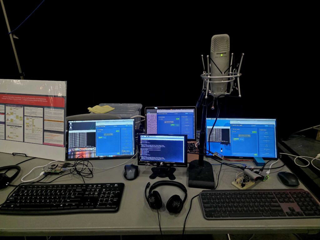
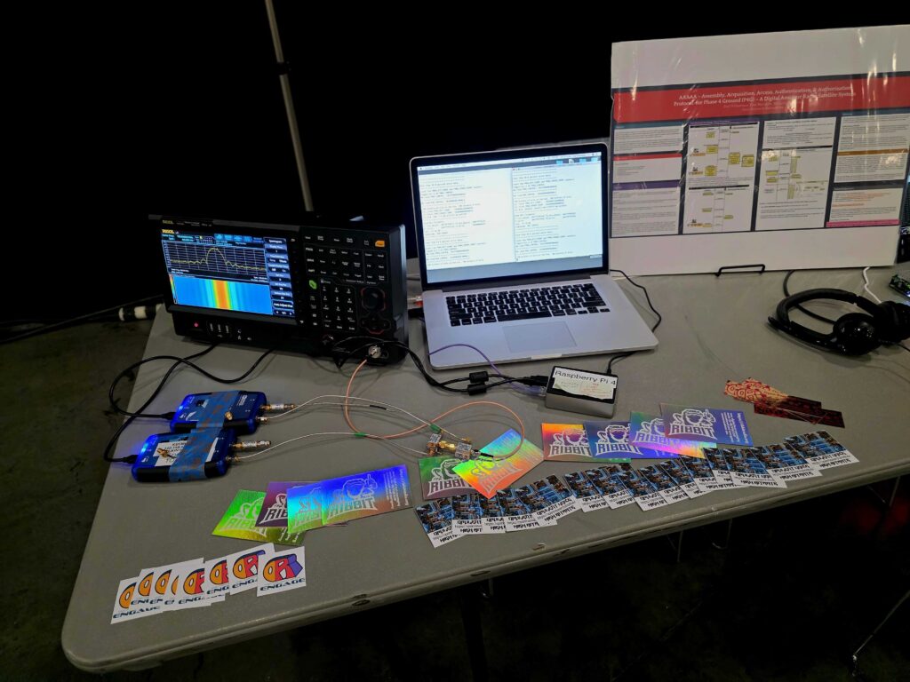
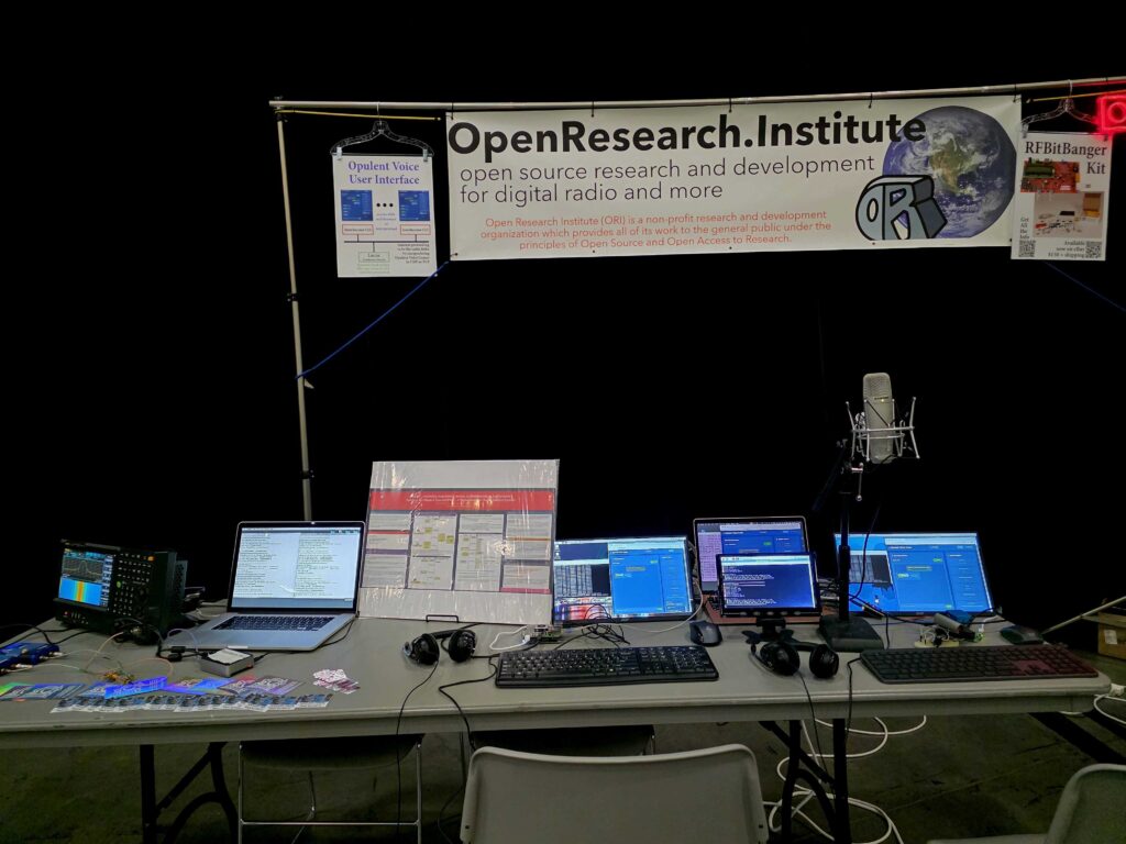
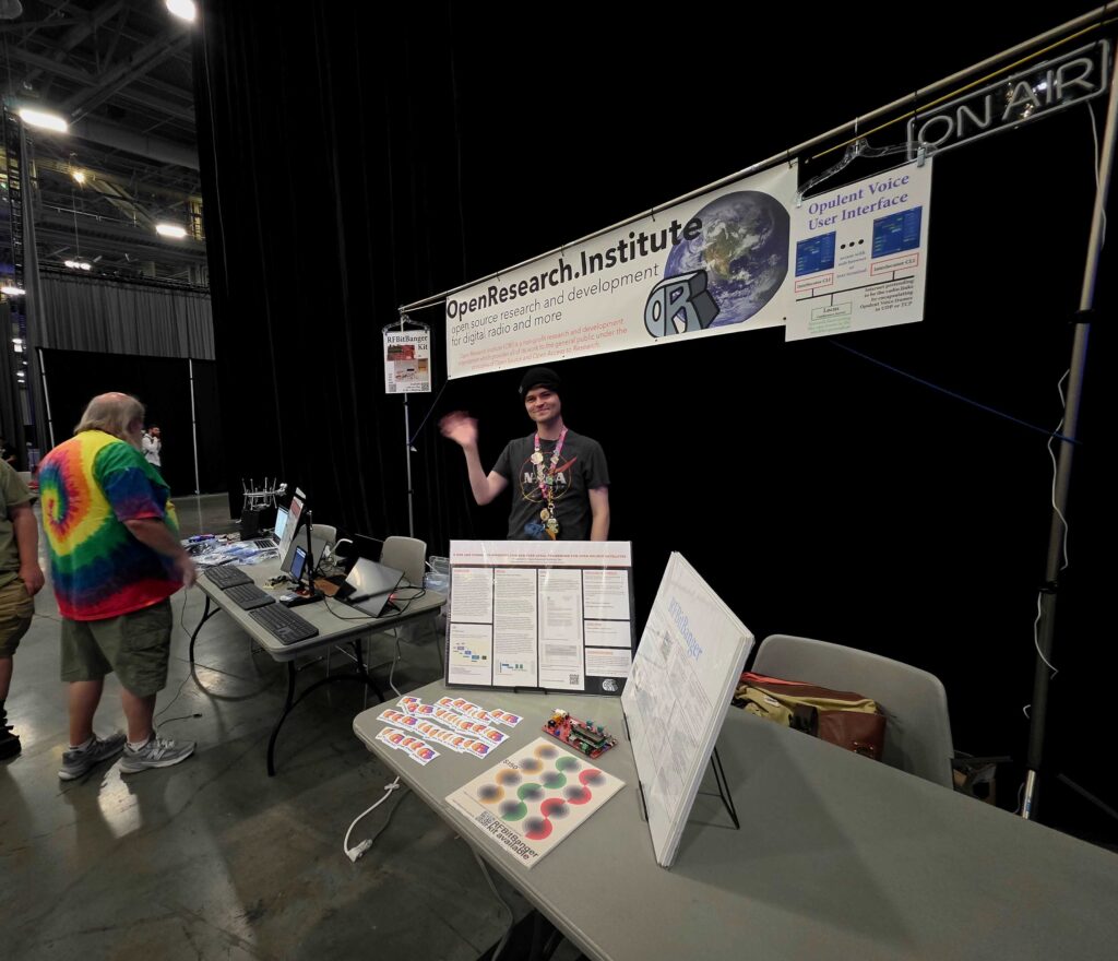
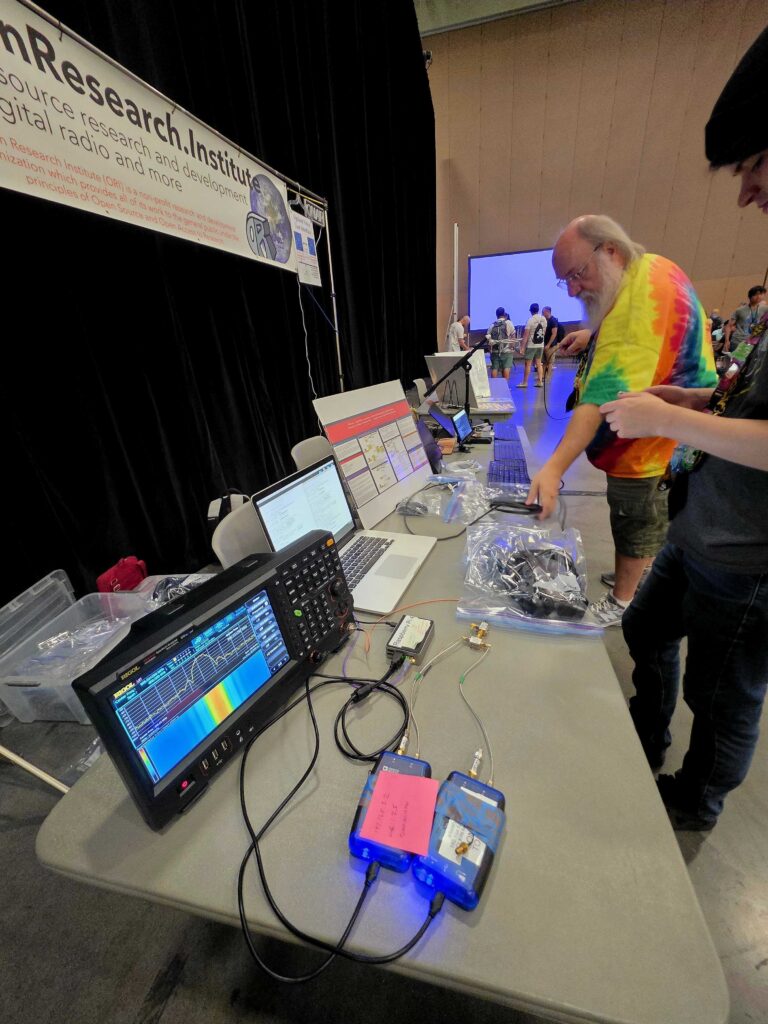
ORI Open Source Digital Radio at DEFCON
by KK6OOZ
At DEFCON in RF Village, we had a place to demonstrate work from ORI. We showed off open source synthetic aperture radar with coffee cans and GNU Radio and a PLUTO, and had space to show our “FT8 performance for keyboard chat” RFBitBanger QRP HF kit. We had room for the regulatory work for ITAR/EAR/219 MHz. And, very importantly – we had enough space to show major components of our UHF and up comms Opulent Voice system for amateur terrestrial and satellite fully up and running. At DEFCON, we had the human-radio interface and the modem as separate fully functional demonstrations.
Today, these two components have been combined and are working end-to-end. It’s coughing and sputtering, but it’s a solid first light. This means that microphone/keyboard/data processing from user input to waveforms over the air are happening.
The design goals for Opulent Voice project are to deliver very good voice quality in a modern way. AMBE/CODEC2 honestly sound terrible. Amateur radio deserves better audio quality. Therefore, we baseline Opus 16 kbps. It sounds great. Want more? there’s a path to 32 kbps.
We were very tired of a separate broken packet mode for data in ham digital voice product after ham digital voice product. Opulent Voice has keyboard chat and data in a single prioritized stream. No separate clunky packet mode. No 1980s architecture. It just works. In your browser. Or, at a command line interface. Chat only with transcriptions of all the audio received? With a microphone all in your ears and you never have to look at a screen? Your choice.
There are transcriptions for received audio (if you want that – it’s configurable), and text to speech for text messages is literally the next issue to be addressed. Accessibility is designed in from the start.
For terrestrial use, we have a demonstration conference server running on ORI’s Linode instance. This was up and running for DEFCON. It’s internet-only implementation of the repeater for terrestrial or space use, so that folks can see what the UI/UX looks like.
Everything is open source. Upcoming events? Opulent Voice will be presented to the ESA, AMSAT-DL, JAMSAT, and others in the next few months.
To everyone here that’s been supportive and wonderful – thank you so much.
RF Village has been instrumental and irreplaceable for this work to get a wider audience. This has been of enormous help. The benefits last year-round.
We’ve exhibited, presented, and contributed towards Ham Radio Village as well.
Here’s where we’ve been publishing and documenting the work. Under active development. Approach with the usual caution.
https://github.com/OpenResearchInstitute/interlocutor human-radio interface
https://github.com/OpenResearchInstitute/dialogus frames-to-modem application code for PLUTO SDR. Accepts Interlocutor connections and delivers them to the PLUTO Opulent Voice modem.
https://github.com/OpenResearchInstitute/pluto_msk Locutus, the award-winning modem firmware for the PLUTO SDR that makes the Opulent Voice waveforms.
Want to set up your own repeater for Opulent Voice?
https://github.com/OpenResearchInstitute/locus
Want to be more involved or informed about our work?
Opulent Voice in Space
Here’s Opulent Voice on a sounding rocket (RockSat-X project). Thank you to University of Puerto Rico for being such a great educational partner! Nice clean signal the entire time.

“Take This Job” For August 2025
Interested in Open Source software and hardware? Not sure how to get started? Here’s some places to begin at Open Research Institute. If you would like to take on one of these tasks, please write hello@openresearch.institute and let us know which one. We will onboard you onto the team and get you started.
Opulent Voice:
Add a carrier sync lock detector in VHDL. After the receiver has successfully synchronized to the carrier, a signal needs to be presented to the application layer that indicates success. Work output is tested VHDL code.
Bit Error Rate (BER) waterfall curves for Additive White Gaussian Noise (AWGN) channel.
Bit Error Rate (BER) waterfall curves for Doppler shift.
Bit Error Rate (BER) waterfall curves for other channels and impairments.
Review Proportional-Integral Gain design document and provide feedback for improvement.
Generate and write a pull request to include a Numerically Controlled Oscillator (NCO) design document for the repository located at https://github.com/OpenResearchInstitute/nco.
Generate and write a pull request to include a Pseudo Random Binary Sequence (PRBS) design document for the repository located at https://github.com/OpenResearchInstitute/prbs.
Generate and write a pull request to include a Minimum Shift Keying (MSK) Demodulator design document for the repository located at https://github.com/OpenResearchInstitute/msk_demodulator
Generate and write a pull request to include a Minimum Shift Keying (MSK) Modulator design document for the repository located at https://github.com/OpenResearchInstitute/msk_modulator
Evaluate loop stability with unscrambled data sequences of zeros or ones.
Determine and implement Eb/N0/SNR/EVM measurement. Work product is tested VHDL code.
Review implementation of Tx I/Q outputs to support mirror image cancellation at RF.
Haifuraiya:
HTML5 radio interface requirements, specifications, and prototype. This is the primary user interface for the satellite downlink, which is DVB-S2/X and contains all of the uplink Opulent Voice channel data. Using HTML5 allows any device with a browser and enough processor to provide a useful user interface. What should that interface look like? What functions should be prioritized and provided? A paper and/or slide presentation would be the work product of this project.
Default digital downlink requirements and specifications. This specifies what is transmitted on the downlink when no user data is present. Think of this as a modern test pattern, to help operators set up their stations quickly and efficiently. The data might rotate through all the modulation and coding, transmitting a short loop of known data. This would allow a receiver to calibrate their receiver performance against the modulation and coding signal to noise ratio (SNR) slope. A paper and/or slide presentation would be the work product of this project.
Inner Circle Sphere of Activity
If you know of an event that would welcome ORI, please let your favorite board member know at our hello at openresearch dot institute email address.
1 September 2025 Our Complex Modulation Math article will be published in ARRL’s QEX magazine in the September/October issue.
5 September 2025 – Charter for the current Technological Advisory Council of the US Federal Communications Commission concludes.
19-21 September 2025 – ESA and AMSAT-DL workshop in Bochum, Germany.
3 October 2025 – Deadline for submission for FCC TAC membership.
10-12 October 2025 – See us at Pacificon, San Ramon Marriot, CA, USA.
11-12 October 2025– Presentation (recorded) to AMSAT-UK Symposium
25-26 October 2025 – Open Source Cubesat Workshop, Athens, Greece.
Thank you to all who support our work! We certainly couldn’t do it without you.
Anshul Makkar, Director ORI
Keith Wheeler, Secretary ORI
Steve Conklin, CFO ORI
Michelle Thompson, CEO ORI
Matthew Wishek, Director ORI
2 Replies to “Inner Circle Newsletter August 2025”