Successfully debuted at BSides San Diego 2026, ORI’s Lunar Descent CTF has been updated with additional documentation and example solutions
One of the many activities that we do at ORI is to participate in and host contests and puzzles. Capture the Flag competitions (CTFs) are a particular type of competition commonly encountered in the cybersecurity and hacking communities. CTFs pose a set of challenges for participants to solve, often drawn from a particular theme or subject. CTFs can be tackled by individuals, but the interdisciplinary and complex nature of many CTFs require a team working together in order to score enough points to be at the top of the leader board.
The Lunar Descent CTF debuted at BSides San Diego, held at San Diego State Univsity on 4 April 2026. This is an ORI original, and all documents can be found on GitHub at https://github.com/OpenResearchInstitute/lunar-descent-ctf. The CTF is based on a real signal processing problem in a radar altimeter.
ISRO’s KaRA radar altimeter guided Chandrayaan-3 to a soft lunar landing on 23 August 2023. The Radar Altimeter Processor (RAP) computes altitude and velocity from FMCW chirp signals, running on a single Xilinx Virtex-5 FPGA. This CTF uses a Python model of that system, faithful to the published paper, where the altimeter feeds a landing autopilot. The altimeter works perfectly. However, once the system was operational, the autopilot keeps crashing in last-minute testing. Why? The answer is the solution to the CTF.
The Lunar Descent CTF is self-scoring and self-paced, which reduced the workload of the booth volunteers. A copy of the IEEE Aerospace and Electronics System Society Magazine article that inspired the CTF was available for people to read. ORI-themed USB drives with a copy of the CTF repository contents were given away to anyone that wanted one to take home with them. The CTF attracted a lof of attention at the ORI-supported RF Village at BSides San Diego, and reviews from participants were very good. While it was anticipated that some participants would be able to solve the CTF in two hours or so, it took the first place winner most of the day, as they wanted to see all the other villages at BSides, and also attend talks. The self-paced “take home” format greatly reduced the pressure on the participants to commit to a contest over seeing the rest of the show. We received positive feedback about this decision, and will use the self-scoring and self-paged methodology in future CTFs. This approach was inspired by the self-scoring BLE CTF, which can be found at https://github.com/hackgnar/ble_ctf
If you would l like to try the CTF, then clone the lunar-descent-ctf repository, start with the top-level README.md, and avoid looking in the spoilers/ directory. The spoilers/ directory has a README file for staff running the event, detailed directions on how to score challenge #1, and also has two example solutions for challenge #2 and challenge #3. Since the solutions are tucked away into a separate directory, one can clone the repository and attempt the CTF without accidentally seeing any of the solutions or hints. However, if you get stuck, or want to compare your solution to the example solutions, all you need to do is drop down into the spoilers/ directory and read through the documentation and solutions.
If you want to use this CTF at your own event, please feel free to clone it and adapt it for your setting and audience.
All the articles from the March 2026 Inner Circle Newsletter in one place.
The Case of the Missing Transmit Power
How a 4-bit Misalignment Stole 24 dB from the Opulent Voice Modem
The Opulent Voice modem for the LibreSDR graduated from the lab to the field in late March 2026. Instead of coaxial cables connecting transmitter to receiver, and receiver to transmitter, we now connected our brave little radios to filters and outdoor antennas.
And, nothing was received. The signal levels appeared to be very low. Even moving the antennas right next to each other resulted in only a few scattered frames demodulated and decoded.
Obviously, we needed an amplifier. Fortunately, we had plenty in stock from collaborating with University of Puerto Rico’s RockSatX team. They used an earlier version of Opulent Voice on their sounding rocket.
From the original listing at https://www.ebay.com/itm/363233702995
————————————————— Microwave RF Power Amplifier Board SBB5089+SHF0589 40MHz-1.2GHz Gain 25DB 10PCS
Specifications:
– Input voltage: 10~30V DC – Input power: about 5W – Working frequency: 40MHz~1.2GHz (0.04~1.2GHz) – Gain: about 25dB (may be higher) – Power: 2W (may be higher)
Attention:
We measured 80.7% ultra-high efficiency in tests, and the official chip manual also mentioned that there is more than 50% efficiency at P1dB. Overall, this SBB5089+SHF0589 is better than SBB5089+SHF0289. —————————————————
On 24 March 2026, we selected one of the amplifiers at random in order to characterize it in ORI’s Remote Labs. We connected the input of the amplifier to the output of the DSG821A signal generator. The signal generator was set to 431 MHz, which was the frequency we wanted to use. We connected the output of the amplifier through a 6 dB attenuator to the Rigol RSA5065N Spectrum Analyzer. We fitted a JST-HX power cable to the power connector of the amplifier. We provided 12 volts of power from the DP832 lab power supply.
The amplifier made 27 dB of gain from -100 dBm input to about -3 dBm input, made 20 dB at 0 dBm input, and worked pretty well up to 9 dBm input.
The next test was to remove the signal generator and connect a LibreSDR running Opulent Voice. Instead of a carrier wave from the signal generator we’d be sending an 81 kHz wide minimum shift key (MSK) signal from a real modem through the amplifier. We were intending to repeat the measurements we’d made with the signal generator. However, we noticed something very interesting. The signal level from the LibreSDR was expected to be about 0 dBm, which would provide enough drive to the amplifier to create enough gain to help our over-the-air tests succeed. However, when the LibreSDR, running Locutus and Dialogus, was commanded to transmit with PTT and audio frames from Interlocutor, the peak of the main lobe of the MSK signal was at 1 microwatt. If this was the true power output of the LibreSDR, then no wonder the over-the-air tests had failed.
The transmit power hardware attenuation setting was confirmed to be at 0 dB. This is set through an Industrial Input and Output (IIO) library attribute call, was correctly reported, and we saw that changing the attribute caused the signal to increase or decrease by the exact amount of gain. So, it wasn’t a configuration error. As far as the hardware was concerned, it was transmitting at 0 dBm.
The other possibility was that the I and Q signals were not being generated for transmit at full scale. If we weren’t filling up the registers correctly, then maybe we were accidentally dividing our signal down before it got to the antenna. Investigation turned to the Hardware Descriptive Language (HDL) files.
The Opulent Voice VHDL language modem, called Locutus, runs inside the LibreSDR FPGA. Data frames arrive via direct memory access, pass through the Opulent Voice frame encoder, are convolutionally encoded (K=7, rate 1/2), go through a byte-to-bit deserializer, and the resulting bits are sent to the MSK modulator. The modulator produces the I and Q samples that drive the AD9363 digital to analog converter (DAC). Software in the general purpose processor of the LibreSDR configures the IIO context and controls PTT.
The direct memory access transfers protocol data frames into the LibreSDR, and not IQ samples. So, the classic PlutoSDR bug of 12-bit samples being miscounted in a 16-bit word did not apply here. The modulator itself generates all I and Q waveforms. The frequencies are set by Dialogus at startup.
The Integrated Logic Analyzer (ILA) in the bitstream already had probes on two very important signals, tx_i_sync and tx_q_sync. These signals were measured right at the point where the samples enter the AD9361 core. A January 2026 ILA capture told the story clearly. The waveform showed clean MSK signals. No corruption, no skips, and with the exact right relationship to each other. At the time, this was a big milestone and part of the process of troubleshooting the porting of the HDL code from the PlutoSDR to the LibreSDR. But we’d overlooked something critical. The bug was right there in an otherwise perfect image.
The peak values of the I and Q waveforms were only plus and minus 1100 or so, in a 16-bit signed word. At first glance, a value of 1100 in a 16-bit word might not raise any red flags. The alarm bells ring when you know how the axi_ad9361 core actually reads those 16 bits.
There are two different conventions on the same bus. The axi_ad9361 core uses 16-bit data buses internally. However, the AD9361 and AD9363 (the chips used in these software-defined radios) have only 12-bit digital to analog converters. The documented convention, confirmed by a tour through Analog Devices Engineer Zone forum, is as follows.
RX (ADC Output) is 12-bit value in [11:0], sign extended to [15:12] TX (DAC Output) is 12-bit value expected in [15:4], which is the top 12 bits
In plain English, RX gives you the data right-justified. TX expects it left-justified. These are opposite conventions on the same 16-bit bus, and the apply whether the interface is CMOS (PlutoSDR) or LVDS (LibreSDR).
Our code, from msk_modulator.vhd, in the carrier_mod_proc section looks like this.
s1s and s2s are each signed 12-bit values from the numerically controlled oscillator (NCO). The lookup table fills using the command
ROUND(SIN(theta) * 1024.0)
which gives a peak value of plus or minus 1024. VHDL addition of two such values produces a 12-bit result that ranges from -2048 to +2048. So far so good. The resize call then sign-extends that 13-bit result into 16 bits. This is a right-justified 16-bit word, which is the opposite of what the Analog Devices core expects.
The full chain of what happens to the signal amplitude can be calculated.
The lookup table output is [11:0] signed and is a 12-bit sinusoid. s1s + s2s is [12:0] signed and is a 13-bit sum. Resize(…, 16) [15:13] sign extension with [12:0] as the data. This is right-justified. Analog Devices chip reads transmit values as [15:4], sending the top 12 bits to the DAC. Analog Devices reads [15:4], we drive [12:0], and this is a divide by 16 to the amplitude.
What’s the damage? -24 dB.
Why did this work in the PlutoSDR? Well, it didn’t. It did not produce full power, either. The same modulator code drove the Pluto variant of Opulent Voice. The -24 dB bug was there too. Why did we not notice it? We never graduated to over-the-air tests with the PlutoSDR. All of the tests transmissions were in the lab and were either conducted through coaxial cables or done with Vivaldi lab antennas right next to each other on the bench. With conducted tests, everything worked perfectly.
For ORI’s LibreSDR work, we were now in the field. We wanted to characterize the modem output before adding an amplifier. That scrutiny revealed the long-lived bug in the HDL.
Matthew Wishek NB0X implemented a fix on the tx_sample_scale branch of the published repository, with changes to two submodules, the NCO and the msk_modulator. No changes to the block design TCL or to msk_top.vhd were required.
In the NCO (sin_cos_lut.vhd), a new constant was introduced: CONSTANT FULL_SCALE : INTEGER := 2**(SINUSOID_W-1) -1. And, the lookup table fill function was changed from the hardcoded 1024.0 to * real(FULL_SCALE). With SINUSOID_W = 12, this gives FULL_SCALE = 2047, filling the entire signed 12-bit range. The fix is fully generic. It works for any value of SINUSOID_W.
In the modulator (msk_modulator.vhd), a new 3-bit input port tx_shift : IN std_logic_vector(2 DOWNTO 0) was added. The IQ output assignment was changed from a plain resize() to a shift_left() whose amount is driven by tx_shift at runtime.
The full 12-bit scale was achieved. With the sum now peaking at plus or minus 4094, left-shifting by 3 puts the signal in the correct place, which is [15:3]. The Analog Devices core reads [15:4], which is the full DAC scale. Making tx_shift a configurable port rather than a hardcoded constant is an elegant touch. Dialogus sets it through the register map at runtime, with no bitstream rebuild needed.
With the tx_sample_scale fix integrated and a new bitstream loaded, the Opulent Voice modem then achieved its first successful over the air transmission. This was from one building to another, with the full signal chain, from a LibreSDR to another LibreSDR. Voice traffic and text messages were received, with excellent audio quality. The ~30 dB shortfall that had been quietly sitting in the hardware since the original modulator was gone.
Lessons Learned
RX and TX use opposite justify directions in axi_ad9361. This is documented, but really only in a so-called Verified Answer on Analog Devices Engineer Zone forum. It’s not prominently documented in the IP wiki. The wiki describes the 16-bit data base and mentions that the IP “always works in 16 bits”, but does not call out the left/right justification asymmetry in a way that is easy to find. If you are writing custom HDL that drives DACs, then you should read the forum thread at https://ez.analog.com/fpga/f/q-a/112155/axi_ad9361-data-format
ILA probes are worth their cost. The screenshot from the ILA capture back in January 2026 told us the answer, if we had known what the question was. Running ILA and keeping the results pays off because you can go back and look at signals that may not be accessible otherwise. Wire up ILA early and often and be curious about your signals. Go for a tour. Explore your design and the design of any infrastructure that you are working with.
-24 dB is a recognizable signature. In fact, any multiple of -6 dB is significant. Each bit of DAC resolution is 6 dB, so if you’re missing something like 24 dB, then an inadvertent four-bit shift might be the culprit.
Fix things at the right layer. The initial discussions included assumptions such as “the fix should live in the block design TCL file” or maybe in msk_top. Matthew chose to fix it inside the modulator and NCO submodules. This is the better choice. It makes the modules self-consistent, removes the need for platform-specific fancy workarounds or settings, and ensures that any future target automatically benefits. When a submodule’s output format is wrong, fix the submodule rather than papering over it at the integration layer.
Acknowledgements
The modulator and NCO were written by Matthew Wishek NB0X, whose clean modular architecture made the bug straightforward to trace, and whose tx_sample_scale branch fix resolved it elegantly at the right layer. Thanks to the ADI FPGA team (Laszlo) for the EngineerZone Verified Answer that became our primary citation. Thanks to Paul KB5MU and Michelle W5NYV for working through this signal chain, characterizing the amplifier, and methodically testing the new firmware.
February 2026 Storm Takes Down Communications Infrastructure on Mount Laguna, CA, USA
by Sudoku Ham for ORI
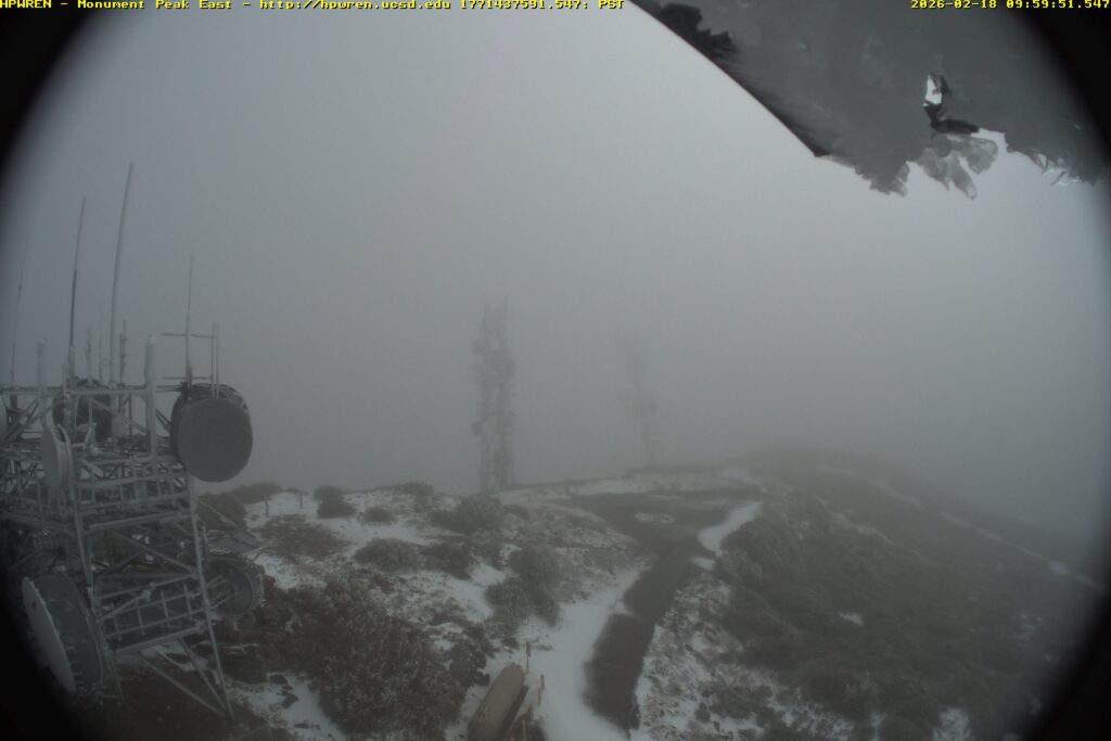
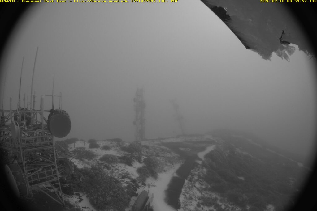
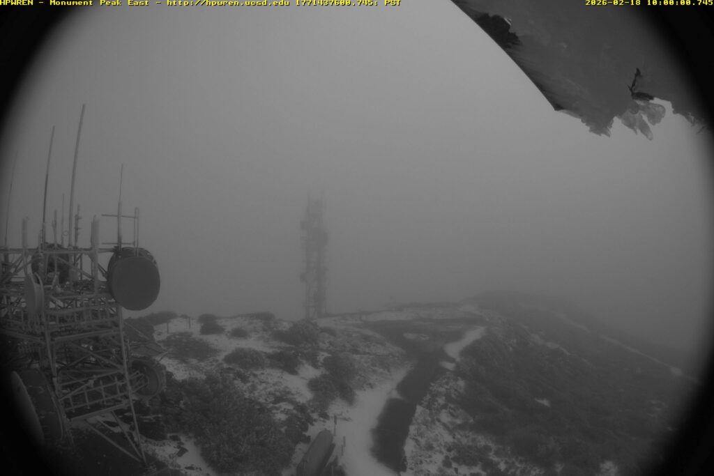
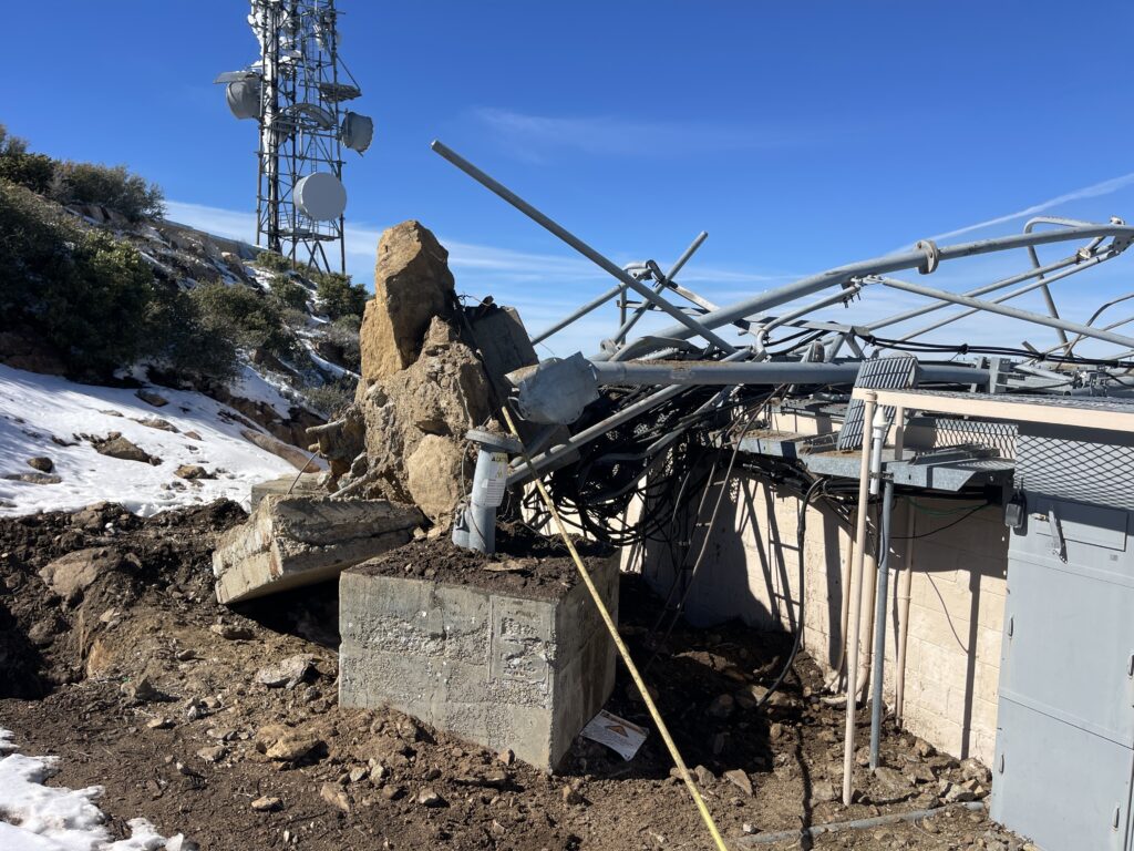
At exactly 10:00 AM on Wednesday, February 18, 2026, a communications tower on Monument Peak in the Laguna Mountains was blown over during a powerful wind event, captured in real time by a nearby wildfire camera system. The tower, owned by American Tower Corporation (ATC), had been carrying an AT&T cellular site and several microwave hops. According to sources familiar with the site, that was the only functional equipment on the structure at the time of its collapse.
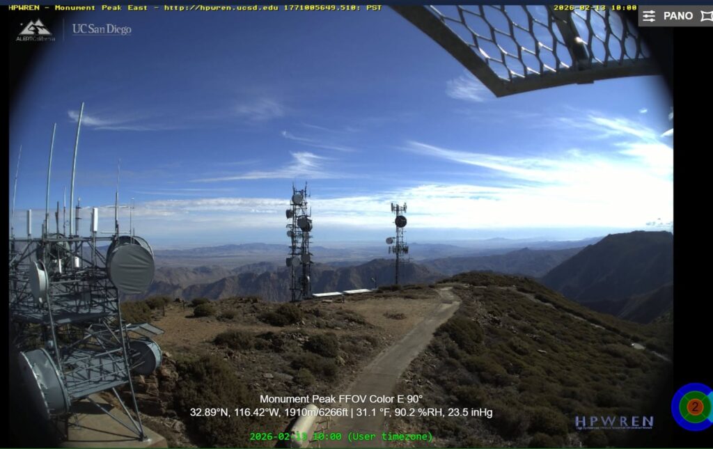
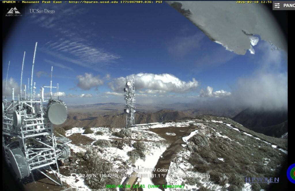
The failure was documented by the HPWREN (High Performance Wireless Research and Education Network) camera system. This system is operated by UC San Diego’s San Diego Supercomputer Center. Video assembled from the east-facing fixed-field-of-view camera shows a major wind event immediately preceding the collapse, with the tower going over at 10:00 AM. A before-and-after comparison of HPWREN still frames, one from February 13 showing the tower standing, another from later on February 18 showing it gone, confirms the loss. Snow visible in the post-collapse image and on the wreckage is consistent with the heavy winter weather that preceded the failure.
Hans-Werner Braun, Research Scientist Emeritus at UCSD, provided additional HPWREN images. Hans-Werner is deeply involved with HPWREN, having served as Principal Investigator. “These are from the 10 second data that we additionally collect for a small subset of the cameras.”
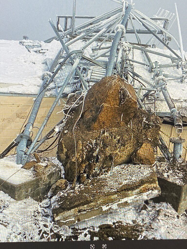
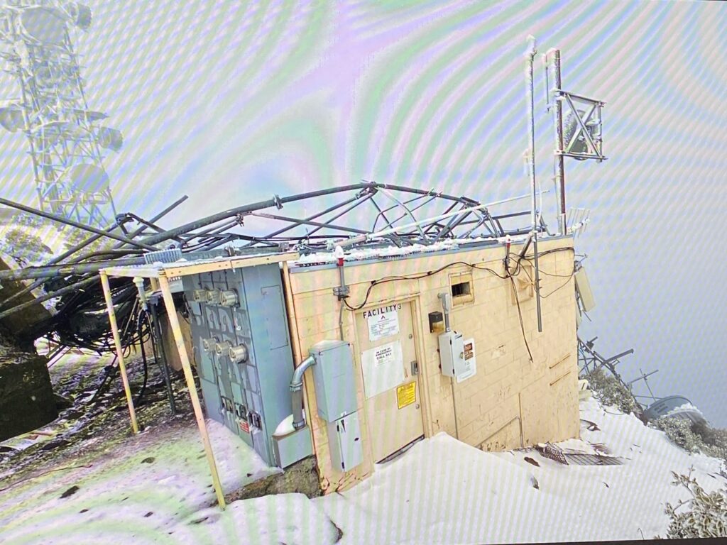
Damage photos obtained from CORA (Cactus Open Repeater Association) members, originally shared by Chris Baldwin, show the aftermath in stark detail. A lattice tower structure torn from its concrete foundation, the base ripped out of the ground with rebar exposed, and the wreckage draped across an equipment shelter labeled “FACILITY 3.” The concrete pier appears to have failed catastrophically, with the entire foundation block uprooted rather than the tower buckling above the base. The combination of snow and ice loading on the structure, high sustained winds, and the age of the tower and presumed lack of recent maintenance all contributed to the failure.
Steve Hansen, W6QX, first drew attention to the HPWREN imagery showing the tower’s disappearance.
The Storm
The collapse occurred during a series of storms that struck San Diego County over the span of four days. The first wave hit Monday, February 16, bringing heavy rain and winds gusting to 60 mph on Mount Laguna. A second, more intense wave arrived overnight Tuesday into Wednesday, the morning the tower fell. That wave produced winds of 80 mph at El Cajon Mountain, measured at 3:30 AM. Wind was measured at 76 mph at Birch Hill in the San Diego County mountains, and at 52 mph in the desert. The National Weather Service reported snow accumulations approaching a foot on Mount Laguna, with additional snow bands continuing through February 19. A third and final round brought further showers and gusty winds on Thursday the 19th before conditions improved Friday.
The HPWREN camera overlay on the February 18 image recorded conditions at Monument Peak of 31.1°F, 90.2% relative humidity, and 23.6 inHg barometric pressure. It was cold, and the front had clearly moved through.
What Was on the Tower?
Monument Peak (32.89°N, 116.42°W, at 6,271 feet) sits at the eastern edge of the Laguna Mountain Recreation Area within the Cleveland National Forest. It is one of the most significant multi-use communications sites in eastern San Diego County, with a coverage footprint extending from the Salton Sea south to the Mexican border and west across the county.
The ATC tower that collapsed was one of multiple structures at the site. The site hosts a diverse set of users and systems. Services known to operate from Monument Peak include the following.
Amateur Radio: The East County Repeater Association (ECRA) operates several repeaters from the Monument Peak site, including 147.240 MHz (+ offset, PL 107.2 Hz. K6KTA, which is a joint effort with CORA that participates in the CalZona Link), 446.750 MHz (- offset, PL 107.2 Hz), and 449.180 MHz (- offset, PL 88.5 Hz). These repeaters appear to have been on a different structure than the one that fell. Operators are encouraged to confirm current status on the air.
HPWREN/ALERT: This system from UC San Diego operates fixed-field-of-view and pan-tilt-zoom wildfire detection cameras, microwave backbone links, and a weather sensor suite from the site. Monument Peak is a backbone node in the HPWREN network and has been since the project transitioned from nearby Stephenson Peak. The HPWREN cameras that documented this collapse were themselves mounted on a separate structure and survived.
NASA Space Geodesy: The Monument Peak compound hosts NASA’s MOBLAS-4 Satellite Laser Ranging (SLR) system, which has operated from this location since 1981, along with a GNSS antenna and an EarthScope seismic station.
Commercial and Public Safety: There are multiple microwave relay dishes and panel antennas visible in the HPWREN imagery on surviving structures. Historical records show San Diego County Sheriff’s Office VHF low-band repeater infrastructure at the site dating to the 1960s.
According to sources familiar with the site, the only functional equipment on the collapsed ATC tower was the AT&T cell site and its microwave backhaul links. The full inventory of what had previously been on the structure versus what was still active is not entirely clear, but the tower appears to have been underutilized at the time of its failure.
What We Know and What We Don’t
The video from the HPWREN cameras answers the biggest question. When did it fall? At 10:00 AM on February 18, during the second and most intense storm wave. Sources who have viewed the time-lapse describe it as showing a clear wind event immediately before the collapse. As is often the case with periodic camera captures of structural failures, the tower is there one frame and gone the next.
What was the failure mode? The damage photos show the concrete foundation pier uprooted from the ground rather than the tower folding at a structural joint. Whether ice loading, sustained wind, a gust event, or a combination caused the failure is unknown. No formal engineering assessment has been publicly released, but commenters seem surprised about the relatively small amount of concrete that was pulled up.
What services are currently offline? The ECRA repeaters and HPWREN systems appear to have survived on other structures. The primary loss appears to be AT&T cellular coverage and microwave backhaul from this site. Operators in the coverage area, particularly in eastern San Diego County and the Imperial Valley, may have noticed cellular outages.
What Happens Next
The central question is whether American Tower Corporation will rebuild. As one source familiar with the site put it (Chris KF6AJM), the only functional thing on the tower was the AT&T cell site with a few microwave hops. Whether that single-tenant revenue justifies the cost of constructing a new tower at a remote mountaintop location in a national forest, with all the permitting, environmental review, and logistics that entails, remains to be seen. It is not clear if that is profitable enough for ATC to put money into the site.
Mountaintop tower sites in places like the Cleveland National Forest are expensive to build and maintain. Access roads can be difficult in winter. Construction requires Forest Service approval. And the economics of a single-carrier site are thin compared to a multi-tenant tower in an urban area. There has been a long-term trend away from using large mountaintop towers, with capacity replaced by fiber backhaul and fixed wireless broadband. The reason for this is that wide coverage is now less valuable than capacity per user. Higher data rates per commercial cellular user cannot be delivered by one large site covering a large land mass as easily and cheaply as can be delivered with more sites all closer to the ground.
On the other hand, Monument Peak provides cellular coverage to areas of eastern San Diego County and the Imperial Valley that are otherwise difficult to serve. The microwave hops that ran through this tower may also have been part of a backhaul chain serving other sites. The downstream effects of this loss on AT&T’s network in the region are not yet clear.
Monument Peak has weathered storms before. HPWREN documented significant wind damage at their Big Black Mountain relay site in January 2018 during a Santa Ana event with 80-90 mph winds, and the HPWREN team rebuilt that site with an improved design to better withstand future weather. A similar assessment and improved rebuild process will likely be needed here for the commercial tower that fell if the economics support it.
For a site that serves as a critical node in the region’s wildfire detection network, amateur radio infrastructure, scientific instrumentation, and commercial communications, the loss of even one tower could have cascading effects. The coming weeks will tell us more about the extent of the damage, any additional as-yet undiscovered damage on other towers, and the timeline for restoration.
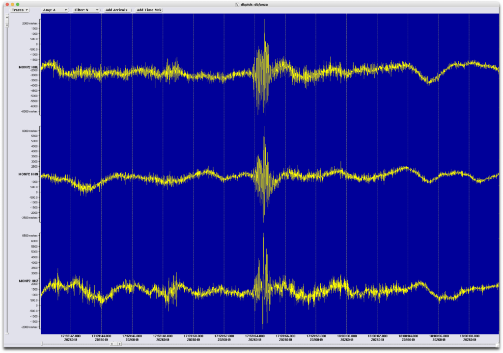
Dr. Frank Vernon, primary investigator for the HPWREN program, confirmed that no HPWREN assets were on the tower that fell. He added via email that UCSD has a seismic station 250 meters from the tower. “Looking at the seismic data”, Dr. Vernon explained, “it looks like we can see the tower hitting the ground.”
Timeline: 09:59:51.5 Color mobo shows tower tilting (see photo from Dr. Werner-Braun above) 09:59:52.1 Monochrome mobo shows tower tilting more (see photo from Dr. Werner-Braun above) 09:59:54 Seismic signal observed
James Davidson (UCSD) provided an additional damage photo, pointing out that “there isn’t much concrete below ‘grade’, and you can also see the rods sticking out, with a big chunk of rock pulled up too.”
If you have additional information about this event, particularly regarding which services are affected or the path forward for restoration, please contact us at ORI. Newsletter signup here: https://www.openresearch.institute/newsletter-subscription/
Photo Credits and Sources
Damage photos: Chris Baldwin, via CORA (Cactus Open Repeater Association) members, and James Davidson (UCSD).
HPWREN before/after camera images: HPWREN Monument Peak FFOV Color E 90° camera, UC San Diego / San Diego Supercomputer Center. HPWREN is funded by the National Science Foundation (Grant Numbers 0087344, 0426879, and 0944131). http://hpwren.ucsd.edu. HPWREN 10-second camera subset imagery from Hans-Werner Braun.
Tip on HPWREN imagery: Steve Hansen, W6QX.
Seismic chart: Dr. Frank Vernon.
Storm data: National Weather Service San Diego (NWS SGX); NBC 7 San Diego; San Diego Union-Tribune; KOGO Newsradio 600; ABC 10News San Diego.
Site information: American Tower Corporation; MRA-Raycom (mra-raycom.com); NASA Space Geodesy Project (space-geodesy.nasa.gov); ECRA (ecra-sd.com); RepeaterBook; N6ACE repeater listings.
Lunar Descent, the BSides San Diego 2026 RF Village Capture the Flag (CTF) from ORI
A capture-the-flag challenge based on a real signal processing problem in a radar altimeter!
Indian Space Research Organization (ISRO) designed a Ka band radar altimeter (KaRA) that guided Chandrayaan-3 to a soft lunar landing on 23 August 2023. The Radar Altimeter Processor (RAP) computes altitude and velocity from FMCW chirp signals, running on a single Xilinx Virtex-5 FPGA. This CTF uses a Python model of that system, faithful to the published paper in the Aeronautics and Electronic Systems Journal, where the altimeter feeds a landing autopilot. In our CTF, the altimeter works perfectly. The autopilot keeps crashing. Why? (solution in next newsletter!)
What did the participants see? A python script that could be installed on their computer and then run.
pip install numpy matplotlib
python lunar_descent_ctf.py --help        # See all options
python lunar_descent_ctf.py               # Run the mission, watch it crash
python lunar_descent_ctf.py --modes       # See the sweep mode table
python lunar_descent_ctf.py --test -p all # Test all three profiles
python lunar_descent_ctf.py --score       # Score your fix and earn flags
Rules
Edit ONLY the `MeasurementQualifier` class (clearly marked in the source)
Don’t change the RAP, signal generation, autopilot, or scoring
The qualifier decides what the autopilot sees — fix it there
Submit flags at the RF Village table
Three Flags
None of the flags are “free”. The buggy code scores 0 / 1000 points out of the box.
Flag
Points
Challenge
RECON
100
Explain the bug to RF Village staff. No hash on screen.
FIRST LIGHT
500
Land all three profiles without crashing.
NO GAPS
400
Zero qualifier rejections on all three profiles.
Total: 1000 points
The Scenario
The radar altimeter was tested on helicopters and aircraft at altitudes above 50 meters. It worked flawlessly. Field test performance met all mission specifications.
The altimeter is now integrated with a landing autopilot that uses both altitude and velocity measurements for thrust control during final approach. In simulation, the autopilot crashes the lander every time below 15 meters altitude. The altitude readings are fine. Sub-meter accuracy all the way to touchdown. Something else is killing the lander.
You need to find out what’s going wrong and fix the measurement qualification logic so the autopilot can land safely.
Difficulty Curve
0 points: Running the code unmodified. The default run shows OK status all the way down until the final approach, then CRASH.
100 points: Explaining the problem to staff.
600 points: Fixing the `MeasurementQualifier` so it can land.
1000 points: Eliminating all qualifier rejections.
Validating Flag 1 (RECON)
No hash is printed on screen for Flag 1. Staff issue the flag manually.
Timing
The CTF ran all day alongside the workshop modules and talks. It’s self-paced and doesn’t require staff attention except for Flag 1 validation and prize distribution.
Test Profiles
Profile
Character
What It Tests
standard
Chandrayaan-3-like smooth descent, 10 km → 3 m, with altitude excursion at 20 m (thruster anomaly or drifting over crater)
Landing
aggressive
Fast exponential braking, 10 km → 3 m in 400 s
Rapid mode transitions at hight altitude + Landing
stepwise
Hover at guard band boundaries (9851/4795/2334/553/131/31/5 m), drop between them
Mode transitions + Low Hover
The Physics
The RAP uses FMCW radar. Up-chirp and down-chirp signals produce beat frequencies:
Altitude comes from the sum: R = M × (f_up_index + f_dn_index). Velocity comes from the difference: fd = (f_dn_index − f_up_index) × freq_res / 2.
The FFT is always 8192 points, but the number of real signal samples depends on the sweep time:
Mode 12 (high altitude): 8192 samples, full FFT Mode 0 (3 m altitude): 14 samples, 99.8% zero-padding
Connection to Real Engineering
The problem is pedagogically framed but the pattern is real. Sensor qualification, knowing when to trust a measurement and when to reject it, is important.
Radar and sonar tracking systems (Doppler reliability vs integration time) GPS/INS integration (knowing when satellite geometry is too poor to trust) Medical imaging (SNR-dependent confidence in measurements) Autonomous vehicle sensor fusion (camera vs lidar vs radar confidence)
The paper mentions “three sample qualification logics to generate the final altitude” without detailing them. What are those logics? Will some of those qualification logics help solve this CTF?
Source
Based on: Sharma et al., “FPGA Implementation of a Hardware-Optimized Autonomous Real-Time Radar Altimeter Processor for Interplanetary Landing Missions,” IEEE A&E Systems Magazine, Vol. 41, No. 1, January 2026. DOI: 10.1109/MAES.2025.3595090
BSides San Diego 2026 RF Village Demonstrations
This is what development looks like!
Open Research Institute organized and executed the RF Village at BSides San Diego on 4 April 2026. This highly anticipated sold-out annual event has a focus on cybersecurity and DIY problem solving. Held at Montezuma Hall at San Diego State University, the one-day event had multiple speaking tracks, at least three Capture the Flag contests (CTFs), an electronic hackable badge, a variety of food and drink available throughout the day, extensive volunteer support, relevant and timely workshops, an After Hours party with more food and drink at Aztec Lanes bowling alley, and a vibrant Village Square that combined Villages and Vendors.
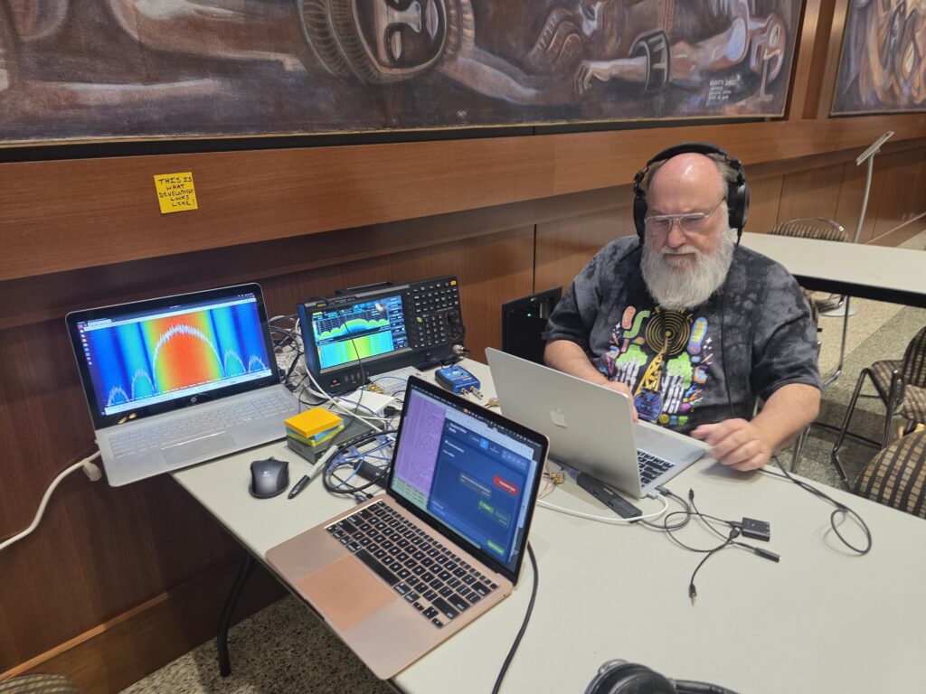
BSides San Diego 2026 RF Village Opulent Voice Development station staffed by Paul Williamson KB5MU. The post it note on the wall says “This is what development looks like!”
ORI served as the organizer for RF Village, bringing four staff members and multiple exhibits. We debuted our Lunar Lander CTF, announced the W6ORI amateur radio club, and gave away a large box of Amateur Satellite handbooks. We had RFBitBanger kits available for donation (5 were sold), hosted a live Meshcore node, and exhibited a real live FPGA development station with lab equipment for Opulent Voice. Our poster session included Authentication and Authorization and the technical side of RFBitBanger. Thank you to BSides San Diego for the excellent support, with rotating village volunteer staffers, volunteer green room, excellent communications before during and after the event, and genuine care for positive participant experience. Organizations like this make demonstrating open source digital radio work a real joy instead of a daunting chore.
Demonstrations give you deadlines, documentations, and get things “done”. The BSides Opulent Voice demonstration revealed some immediate problems with the 24 dB transmitter fix. The signal was clearly being transmitted at sufficient power, but the symbol and frame lock were not happening. We were seeing “garbage” frames where we were expecting to see actual live data.
Since the over-the-air voice call had worked so well just a few days prior, what was going on? The demonstration was still very successful, as plenty could be shown to the steady stream of people at the RF Village. As the day progressed, more information was gathered. It was very clear we’d have to go back to the lab to figure out how a badly needed transmitter fix had broken the receiver. Why was it working over the air, and not in RF loopback on the bench? First, we went back to the VHDL-only test bench. This sends 10 frames into the transmitter, routes the transmit I and Q streams right back to the receiver, and then demodulates, decodes, and displays the frames. The data in should match the data out. And, frames were coming out, but they were completely scrambled! Something had gone wrong in the RF loopback.
The difference between simulations and real life is usually a lot, and Opulent Voice is no different. A real hardware RF loopback has the radio chip in the loop. The VHDL test bench has only the FPGA contents. We don’t have analog to digital converters (ADCs), digital to analog converters (DACs), or anything else that is in the radio chip. Since the transmitter fix had a lot to do with how the transmitter DAC dealt with the data, it seemed reasonable to assume that the transmitter fix had upset the receiver.
The missing gain was in the transmitter, but the fix applied some math changes to both the transmiter and the receiver, and investigating this took up part of the next day back in the lab. WIth two minor changes, the test bench started working flawlessly again. A new version of the firmware was created, and… it didn’t work in hardware at all! Symbol lock and frame lock were totally non-functional. The plot had certainly thickened.
This is one of the many reasons why demonstrations are so valuable. We find things that we might not go looking for, and it forces us to regularly show things working end-to-end. Work continues this week in the lab to separate the transmitter fix from inadvetently affecting the receiver, and bring us back to working perfectly over the air as well as in simulation.
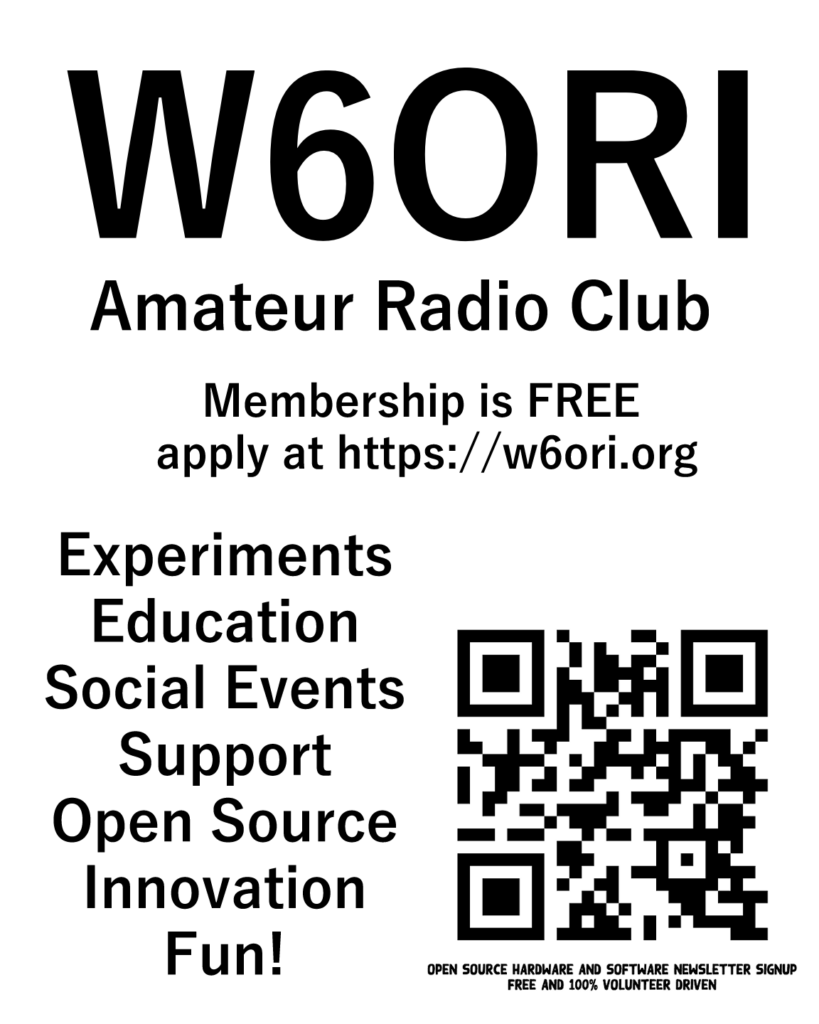
Open Research Institute granted Amateur Radio Club Call W6ORI
ORI now has its very own amateur radio club call. Membership in ORI’s amateur radio club is free. Just sign up for the Inner Circle Newsletter. Below is the poster announcing the debut of W6ORI. The announcement was made in RF Village at BSides San Diego, held at SDSU Montezuma Hall on 4 April 2026.
ORI Invited to Present Open Source Reference Design for IEEE P1954 UAV Communications Standard
Open Research Institute has been invited to present at the IEEE P1954 working group meeting on April 8th. Our topic: how to build an open source reference implementation for the emerging standard on self-organizing, spectrum-agile UAV communications.
What is IEEE P1954?
IEEE P1954 defines architecture and protocols that allow unmanned aerial vehicles to automatically form networks, dynamically access available spectrum, and coordinate communications without centralized infrastructure. Think of it as giving drones the ability to self-organize into mesh networks while intelligently sharing radio spectrum. These are critical capabilities for search and rescue, disaster response, infrastructure inspection, and beyond.
The standard is deliberately technology-agnostic. It specifies what UAV communication systems need to do, not how to build them. That’s where reference implementations come in.
Why Open Source Matters Here
Standards without working implementations remain academic exercises. An open source reference design serves multiple purposes
Experimentation platform: Researchers and developers can test ideas against a working baseline
Conformance validation: Implementers can verify their systems behave correctly
Lowered barriers: Smaller players can participate without building everything from scratch
Vendor neutrality: No single company controls the reference, aligning with the standard’s technology-agnostic philosophy
What ORI Brings to the Table
ORI’s existing work maps remarkably well onto P1954’s architecture. The standard envisions two distinct communication tiers:
Command & Control (C2): Safety-critical links requiring high reliability, low latency, and modest data rates
Payload: High-throughput channels for video and sensor data where best-effort delivery is acceptable
Our Opulent Voice protocol (MSK/CPFSK, constant envelope, narrowband) is designed for exactly the reliability-first requirements of C2 links. Our Neptune OFDM work addresses the high-throughput payload tier. Both have FPGA implementations in progress.
The standard also includes a SHALL-level requirement that UAVs “embed radio equipment such as software defined radios”. This is precisely our domain.
The Path Forward
We’re proposing to bring implementable chunks of P1954 into ORI repositories as open source FPGA and general-purpose processor designs. This isn’t about implementing the entire standard overnight. It’s about identifying the pieces most amenable to open source development and building momentum from there.
The April 16th meeting is our opportunity to discuss this approach with the working group and align our efforts with their priorities.
Get Involved
If you’re interested then this is an opportunity to contribute to an emerging international standard from the ground floor. Watch for updates on our mailing lists and repositories.
Open Research Institute organized and executed the RF Village at BSides San Diego on 4 April 2026. This highly anticipated sold-out annual event has a focus on cybersecurity and DIY problem solving. Held at Montezuma Hall at San Diego State University, the one-day event had multiple speaking tracks, at least three Capture the Flag contests (CTFs), an electronic hackable badge, a variety of food and drink available throughout the day, extensive volunteer support, relevant and timely workshops, an After Hours party with more food and drink at Aztec Lanes bowling alley, and a vibrant Village Square that combined Villages and Vendors.
BSides San Diego 2026 RF Village Opulent Voice Development station staffed by Paul Williamson KB5MU. The post it note on the wall says “This is what development looks like!”
ORI served as the organizer for RF Village, bringing four staff members and multiple exhibits. We debuted our Lunar Lander CTF, announced the W6ORI amateur radio club, and gave away a large box of Amateur Satellite handbooks. We had RFBitBanger kits available for donation (5 were sold), hosted a live Meshcore node, and exhibited a real live FPGA development station with lab equipment for Opulent Voice. Our poster session included Authentication and Authorization and the technical side of RFBitBanger. Thank you to BSides San Diego for the excellent support, with rotating village volunteer staffers, volunteer green room, excellent communications before during and after the event, and genuine care for positive participant experience. Organizations like this make demonstrating open source digital radio work a real joy instead of a daunting chore.
Demonstrations give you deadlines, documentations, and get things “done”. The BSides Opulent Voice demonstration revealed some immediate problems with the 24 dB transmitter fix. The signal was clearly being transmitted at sufficient power, but the symbol and frame lock were not happening. We were seeing “garbage” frames where we were expecting to see actual live data.
Since the over-the-air voice call had worked so well just a few days prior, what was going on? The demonstration was still very successful, as plenty could be shown to the steady stream of people at the RF Village. As the day progressed, more information was gathered. It was very clear we’d have to go back to the lab to figure out how a badly needed transmitter fix had broken the receiver. Why was it working over the air, and not in RF loopback on the bench? First, we went back to the VHDL-only test bench. This sends 10 frames into the transmitter, routes the transmit I and Q streams right back to the receiver, and then demodulates, decodes, and displays the frames. The data in should match the data out. And, frames were coming out, but they were completely scrambled! Something had gone wrong in the RF loopback.
The difference between simulations and real life is usually a lot, and Opulent Voice is no different. A real hardware RF loopback has the radio chip in the loop. The VHDL test bench has only the FPGA contents. We don’t have analog to digital converters (ADCs), digital to analog converters (DACs), or anything else that is in the radio chip. Since the transmitter fix had a lot to do with how the transmitter DAC dealt with the data, it seemed reasonable to assume that the transmitter fix had upset the receiver.
The missing gain was in the transmitter, but the fix applied some math changes to both the transmiter and the receiver, and investigating this took up part of the next day back in the lab. WIth two minor changes, the test bench started working flawlessly again. A new version of the firmware was created, and… it didn’t work in hardware at all! Symbol lock and frame lock were totally non-functional. The plot had certainly thickened.
This is one of the many reasons why demonstrations are so valuable. We find things that we might not go looking for, and it forces us to regularly show things working end-to-end. Work continues this week in the lab to separate the transmitter fix from inadvetently affecting the receiver, and bring us back to working perfectly over the air as well as in simulation.
Indian Space Research Organization (ISRO) designed a Ka band radar altimeter (KaRA) that guided Chandrayaan-3 to a soft lunar landing on 23 August 2023. The Radar Altimeter Processor (RAP) computes altitude and velocity from FMCW chirp signals, running on a single Xilinx Virtex-5 FPGA. This CTF uses a Python model of that system, faithful to the published paper in the Aeronautics and Electronic Systems Journal, where the altimeter feeds a landing autopilot. In our CTF, the altimeter works perfectly. The autopilot keeps crashing. Why? (solution in next newsletter!)
What did the participants see? A python script that could be installed on their computer and then run.
pip install numpy matplotlib
python lunar_descent_ctf.py --help        # See all options
python lunar_descent_ctf.py               # Run the mission, watch it crash
python lunar_descent_ctf.py --modes       # See the sweep mode table
python lunar_descent_ctf.py --test -p all # Test all three profiles
python lunar_descent_ctf.py --score       # Score your fix and earn flags
Rules
Edit ONLY the `MeasurementQualifier` class (clearly marked in the source)
Don’t change the RAP, signal generation, autopilot, or scoring
The qualifier decides what the autopilot sees — fix it there
Submit flags at the RF Village table
Three Flags
None of the flags are “free”. The buggy code scores 0 / 1000 points out of the box.
Flag
Points
Challenge
RECON
100
Explain the bug to RF Village staff. No hash on screen.
FIRST LIGHT
500
Land all three profiles without crashing.
NO GAPS
400
Zero qualifier rejections on all three profiles.
Total: 1000 points
The Scenario
The radar altimeter was tested on helicopters and aircraft at altitudes above 50 meters. It worked flawlessly. Field test performance met all mission specifications.
The altimeter is now integrated with a landing autopilot that uses both altitude and velocity measurements for thrust control during final approach. In simulation, the autopilot crashes the lander every time below 15 meters altitude. The altitude readings are fine. Sub-meter accuracy all the way to touchdown. Something else is killing the lander.
You need to find out what’s going wrong and fix the measurement qualification logic so the autopilot can land safely.
Difficulty Curve
0 points: Running the code unmodified. The default run shows OK status all the way down until the final approach, then CRASH.
100 points: Explaining the problem to staff.
600 points: Fixing the `MeasurementQualifier` so it can land.
1000 points: Eliminating all qualifier rejections.
Validating Flag 1 (RECON)
No hash is printed on screen for Flag 1. Staff issue the flag manually.
Timing
The CTF ran all day alongside the workshop modules and talks. It’s self-paced and doesn’t require staff attention except for Flag 1 validation and prize distribution.
Test Profiles
Profile
Character
What It Tests
standard
Chandrayaan-3-like smooth descent, 10 km → 3 m, with altitude excursion at 20 m (thruster anomaly or drifting over crater)
Landing
aggressive
Fast exponential braking, 10 km → 3 m in 400 s
Rapid mode transitions at hight altitude + Landing
stepwise
Hover at guard band boundaries (9851/4795/2334/553/131/31/5 m), drop between them
Mode transitions + Low Hover
The Physics
The RAP uses FMCW radar. Up-chirp and down-chirp signals produce beat frequencies:
Altitude comes from the sum: R = M × (f_up_index + f_dn_index). Velocity comes from the difference: fd = (f_dn_index − f_up_index) × freq_res / 2.
The FFT is always 8192 points, but the number of real signal samples depends on the sweep time:
Mode 12 (high altitude): 8192 samples, full FFT Mode 0 (3 m altitude): 14 samples, 99.8% zero-padding
Connection to Real Engineering
The problem is pedagogically framed but the pattern is real. Sensor qualification, knowing when to trust a measurement and when to reject it, is important.
Radar and sonar tracking systems (Doppler reliability vs integration time) GPS/INS integration (knowing when satellite geometry is too poor to trust) Medical imaging (SNR-dependent confidence in measurements) Autonomous vehicle sensor fusion (camera vs lidar vs radar confidence)
The paper mentions “three sample qualification logics to generate the final altitude” without detailing them. What are those logics? Will some of those qualification logics help solve this CTF?
Source
Based on: Sharma et al., “FPGA Implementation of a Hardware-Optimized Autonomous Real-Time Radar Altimeter Processor for Interplanetary Landing Missions,” IEEE A&E Systems Magazine, Vol. 41, No. 1, January 2026. DOI: 10.1109/MAES.2025.3595090
Open Research Institute is a non-profit dedicated to open source digital radio work on the amateur bands. We do both technical and regulatory work. Our designs are intended for both space and terrestrial deployment. We’re all volunteer and we work to use and protect the amateur radio bands.
Membership is free. All work is published to the general public at no cost. Our work can be reviewed and designs downloaded at https://github.com/OpenResearchInstitute
We equally value ethical behavior and over-the-air demonstrations of innovative and relevant open source solutions. We offer remotely accessible lab benches for microwave band radio hardware and software development. We host meetups and events at least once a week. Members come from around the world.
The Microwave Link Mystery Puzzle (Solution Below)
Four amateur radio operators (Alice, Bob, Carol, and Dave) are setting up 10 GHz microwave links. Each has a different antenna polarization: Horizontal, Vertical, Right-Hand Circular (RHC), and Left-Hand Circular (LHC).
Polarization Loss Rules
Same polarization: 0 dB loss
Cross-polarized linear (H vs V): 20+ dB loss
Circular to linear: 3 dB loss (either direction)
Opposite circular (RHC vs LHC): 20+ dB loss
The Clues
1. Alice can communicate with Bob with perfect signal strength (0 dB loss).
2. Alice gets terrible reception from Carol (20+ dB loss).
3. Alice receives Dave’s signal at reduced power (3 dB loss).
4. Bob can barely hear Carol (20+ dB loss).
5. Bob gets a good but reduced signal from Dave (3 dB loss).
6. Carol receives Dave’s signal at reduced power (3 dB loss).
7. One operator forgot to rotate their new IC-905 dish from its factory vertical polarization setting.
8. Bob notices that a 10 degree rotation resulted in a lot of signal loss.
Who has which antenna polarization?
Solution:
Alice: Horizontal
Bob: Horizontal
Carol: Vertical (IC-905 factory setting – forgot to rotate!)
Dave: Right-Hand Circular (RHCP)
From clue 1, Alice and Bob have 0 dB loss, therefore they have identical polarization.
From clues 2 & 4, both Alice and Bob get 20+ dB loss from Carol, so Carol has the orthogonal polarization to Alice/Bob. This 20+ dB loss could happen in two scenarios:
1. Alice/Bob are one linear polarization (for example, Horizontal), Carol is the orthogonal linear (for example, Vertical).
2. Alice/Bob are one circular polarization (for example, RHCP), Carol is the opposite circular (for example, LHCP).
From Clue 8, Bob has either vertical or horizontal polarization, as rotating the antenna results in noticeable loss. Rotating a circular polarized antenna doesn’t result in much loss.
From clues 3, 5, & 6, Dave gets 3 dB loss from Alice, Bob, and Carol. Since 3 dB loss occurs between circular and linear polarizations, and we suspect Bob is linear, then Dave must be circular.
Dave can get 3 dB from all three is if Alice/Bob/Carol are all linear polarizations, and Dave is circular.
Then clue 7 (IC-905 vertical) helps us determine which linear polarizations they have.
From clue 7, someone has an IC-905 in vertical polarization. This some “one” must be Carol (since she’s orthogonal to Alice/Bob). Only one operator forgot to rotate, so it can’t be both Alice and Bob with vertical.
Therefore: Carol = Vertical,
Alice/Bob = Horizontal.
Since we have Horizontal (Alice/Bob), Vertical (Carol), and one circular (Dave), Dave must be either RHCP or LHCP. We are going to say RHCP, but it is arbitrary. LHCP is correct too.
Interested in Open Source software and hardware? Not sure how to get started? Here’s some places to begin at Open Research Institute. If you would like to take on one of these tasks, please write hello@openresearch.institute and let us know which one. We will onboard you onto the team and get you started.
Opulent Voice:
Add a carrier sync lock detector in VHDL. After the receiver has successfully synchronized to the carrier, a signal needs to be presented to the application layer that indicates success. Work output is tested VHDL code.
Bit Error Rate (BER) waterfall curves for Additive White Gaussian Noise (AWGN) channel.
Bit Error Rate (BER) waterfall curves for Doppler shift.
Bit Error Rate (BER) waterfall curves for other channels and impairments.
Review Proportional-Integral Gain design document and provide feedback for improvement.
Generate and write a pull request to include a Numerically Controlled Oscillator (NCO) design document for the repository located at https://github.com/OpenResearchInstitute/nco.
Generate and write a pull request to include a Pseudo Random Binary Sequence (PRBS) design document for the repository located at https://github.com/OpenResearchInstitute/prbs.
Generate and write a pull request to include a Minimum Shift Keying (MSK) Demodulator design document for the repository located at https://github.com/OpenResearchInstitute/msk_demodulator
Generate and write a pull request to include a Minimum Shift Keying (MSK) Modulator design document for the repository located at https://github.com/OpenResearchInstitute/msk_modulator
Evaluate loop stability with unscrambled data sequences of zeros or ones.
Determine and implement Eb/N0/SNR/EVM measurement. Work product is tested VHDL code.
Review implementation of Tx I/Q outputs to support mirror image cancellation at RF.
Haifuraiya:
HTML5 radio interface requirements, specifications, and prototype. This is the primary user interface for the satellite downlink, which is DVB-S2/X and contains all of the uplink Opulent Voice channel data. Using HTML5 allows any device with a browser and enough processor to provide a useful user interface. What should that interface look like? What functions should be prioritized and provided? A paper and/or slide presentation would be the work product of this project.
Default digital downlink requirements and specifications. This specifies what is transmitted on the downlink when no user data is present. Think of this as a modern test pattern, to help operators set up their stations quickly and efficiently. The data might rotate through all the modulation and coding, transmitting a short loop of known data. This would allow a receiver to calibrate their receiver performance against the modulation and coding signal to noise ratio (SNR) slope. A paper and/or slide presentation would be the work product of this project.
ORI’s “Real and Complex Signal Basics” Article to be Published in QEX
The September/October 2025 issue of ARRL’s QEX magazine features “Real and Complex Signal Basics” by Michelle Thompson W5NYV. The article provides a step-by-step mathematical explanation of how complex modulation works in digital radio systems.
The piece starts with simple single-carrier real signals and builds up to explain quadrature amplitude modulation (QAM). Using clear mathematical derivations, it shows how two real signals can be transmitted simultaneously using sine and cosine carriers that are 90 degrees out of phase, then separated at the receiver using trigonometric identities and integration.
Subjects covered include:
How real signals create symmetrical frequency domain images
The transition from 4-level amplitude modulation to 16QAM using I and Q coordinates
The mathematical basis for quadrature mixing at both transmitter and receiver
Why complex modulation eliminates unwanted frequency images
How this approach enables higher data rates without requiring finer amplitude resolution
The article emphasizes the practical advantages of complex modulation. You get increased spectral efficiency, easier filtering due to single-sided transmission, and the flexibility to implement any modulation scheme through software-defined radio techniques.
This mathematical foundation underlies much of ORI’s digital radio development work, including the Opulent Voice protocol and other broadband digital communications projects.
The full article is available to ARRL members through QEX magazine. Want to publish it in your club newsletter? Article is available on request from ARRL from qst@arrl.org
Looking to Learn more about IQ Modulation?
Basics of IQ Signals and IQ modulation & demodulation – A tutorial by W2AEW
Opposition to AST & Science LLC (AST SpaceMobile) Request for Amateur Radio Band Usage
July 21, 2025
Executive Summary
We respectfully submit this comment in strong opposition to AST & Science LLC’s (AST SpaceMobile) request to utilize the 430-440 MHz amateur radio band for Telemetry, Tracking, and Command (TT&C) operations for their planned 243-satellite constellation. We urge the Commission to deny this application and direct AST SpaceMobile toward established commercial satellite frequency allocations that are much more appropriate for their commercial operations.
Background and Technical Concerns
First, we have currently unauthorized operations going on. AST SpaceMobile currently operates five Bluebird commercial satellites launched on September 12, 2024, using amateur radio frequencies at 430.5, 432.3, 434.1, 435.9, and 439.5 MHz with 50 kHz bandwidth for telemetry links. This existing operation has already demonstrated the potential for interference with legitimate amateur radio operations.
The scope of the proposed expansion is a problem. AST SpaceMobile seeks to expand this usage to a 243-satellite constellation, with each TT&C beam supporting command and telemetry channels with bandwidths between 64-256 kHz. This massive expansion would fundamentally transform the character of the amateur radio band from experimental and emergency communications to commercial satellite operations.
Amateur Radio uses this band and is important. The 430-440 MHz band serves a variety of critical Amateur Radio applications including amateur space communications, weak-signal SSB, digital television, data communications, repeaters and other applications. The amateur radio service in this band supports:
Emergency Communications: Amateur radio operators provide vital public service during disasters when commercial communications infrastructure fails.
Space Communication: Educational and experimental satellite communications that advance the radio arts.
Technical Innovation: Experimentation and development of new communication technologies. Where do we think new engineers come from? Many of them come from amateur radio.
International Coordination: The proposed constellation will cause interference to amateurs world-wide. This is opposed by a wide variety of international amateur radio organizations.
Regulatory and Precedential Concerns
This is a very inappropriate band allocation. The 430-440 MHz band is allocated to the Amateur Radio Service, not commercial satellite operations. ITU study groups investigated potential TT&C frequency allocations in the frequency ranges 150.05–174 MHz and 400.15–420 MHz, specifically excluding the amateur allocation at 430-440 MHz. Permitting a commercial satellite constellation to operate in amateur radio spectrum sets a dangerous precedent that could lead to further commercial encroachment on bands reserved for experimental, educational, and emergency communications.
Frequency coordination frameworks exist. Satellite frequency coordination, particularly in these frequency bands, relies on a global regulatory and technical framework maintained by the International Telecommunication Union (ITU). AST SpaceMobile should utilize this established framework rather than seeking unauthorized access to amateur spectrum. ITU study results are clear. ITU study groups conducted sharing studies in various bands which yield that no new allocations are suitable for small satellite TT&C on a co-channel sharing basis. Proper commercial allocations exist that would not interfere with amateur operations.
Proposed Alternative Solutions
We recommend the Commission direct AST SpaceMobile to utilize appropriate commercial satellite frequency allocations:
1. S-Band Operations: Migrate TT&C operations to established S-band satellite allocations (2025-2110 MHz and 2200-2290 MHz)
2. X-Band Implementation: Utilize X-band frequencies (8025-8400 MHz) which offer excellent propagation characteristics for satellite communications
3. Ka-Band Adoption: Consider Ka-band frequencies for high-capacity operations
4. Proper ITU Coordination: Work through established international coordination procedures for legitimate commercial satellite spectrum
Technical feasibility is not an issue. Modern satellite technology readily supports operations in these higher frequency bands. The primary frequency bands of S, X, and Ka are more advantageous than using the UHF band, which has a higher probability of local interference.
Economic and Public Interest Considerations
Protecting Public Service is important. Amateur radio operators provide critical emergency communications during disasters. Interference from commercial satellite operations could compromise this vital public service capability. The amateur radio service serves as a proving ground for new technologies and provides STEM education opportunities. Commercial encroachment limits these important societal benefits and harms our national competitiveness.
Precedential impact is negative. Approving commercial use of amateur spectrum without compelling technical justification would invite similar requests from other commercial operators, potentially destroying the character of amateur radio allocations.
Conclusion and Recommendations: We respectfully urge the Commission to:
1. DENY AST SpaceMobile’s request to operate in the 430-440 MHz amateur radio band
2. DIRECT AST SpaceMobile to utilize appropriate commercial satellite frequency allocations in S, X, or Ka bands
3. REQUIRE proper ITU coordination for international satellite operations
4. REAFFIRM the Commission’s commitment to protecting amateur radio spectrum for its intended non-commercial, experimental, and emergency communications purposes
The amateur radio bands serve critical public interest functions that would be compromised by large-scale commercial satellite operations. Abundant alternative spectrum exists that is specifically allocated for commercial satellite TT&C operations. We urge the Commission to preserve the amateur radio bands for their intended purposes and direct AST SpaceMobile toward appropriate commercial spectrum.
References: FCC DA 25-532 (June 20, 2025), AMSAT-UK Technical Analysis, ITU Radio Regulations and Study Reports, and NASA Small Satellite Guidelines
ORI’s Contribution to FCC Technological Advisory Council
Open Research Institute contributed to the US Federal Communications Commission Technological Advisory Council final report for the 2024-2025 term. A summary of ORI’s final draft contribution to the report is presented here.
We describe how spectrum sharing models must evolve to meet growing demand, particularly focusing on terrestrial-satellite integration. The core thesis suggests we’re experiencing a crisis in current spectrum management that requires transitioning to a new “Era 4” model incorporating AI/ML automation and market-based mechanisms.
Historical Evolution of Spectrum Management
We identify three distinct eras of spectrum management.
Era 1 (1890-1912): Unregulated Model – A “loudest-served” system with no regulatory oversight, which collapsed following the Titanic disaster due to communication congestion.
Era 2 (1927-1981): Command-and-Control Model – Centralized FCC authority making static allocations based on “public interest.” This system struggled with emerging technologies like FM radio and cellular networks.
Era 3 (1993-present): Market-Based/Flexible Use Model – Introduced spectrum auctions and flexible licensing, but now showing signs of regulatory overload and crisis.
Evidence of Current Crisis
Several indicators suggest Era 3 regulatory models are failing.
219 MHz Band Limbo: Years of regulatory deadlock between amateur radio, commercial, and federal interests with zero amateur activity despite allocated rights
C-Band Aviation Disputes: $81 billion auction created interference concerns with radar altimeters, requiring presidential intervention
Inter-agency Conflicts: NTIA and FCC reaching opposite conclusions on identical technical evidence (Ligado case)
Reallocation Resistance: Broadcasting industry claiming all “low hanging fruit” has been picked from spectrum repacking
Technical Challenges in Terrestrial-Satellite Sharing
We highlight complex coordination requirements across multiple services in bands like 7.125-8.4 GHz, including Fixed Satellite Service, Mobile Satellite Service, and various terrestrial services. The SiriusXM situation exemplifies ongoing interference challenges between satellite and terrestrial broadband services.
AI/ML Enhanced Spectrum Management
The report positions AI/ML as essential for Era 4, comparing it to sophisticated air traffic control for the electromagnetic domain. Key capabilities include real-time spectrum sensing and occupancy analysis, dynamic allocation based on interference patterns, pattern recognition for optimization, and automated coordination at scale beyond human regulatory capacity
However, the report recommends against mandating specific AI/ML technologies, favoring technology-neutral approaches.
Proposed Era 4 Solutions
Band Managers and Spectrum Bucks: Government exits direct allocation, appointing non-governmental band managers who negotiate usage using a “Spectrum Bucks” currency system. This would enable both commercial and non-commercial users to coexist through market mechanisms.
Amateur Radio Model: Highlighted as a successful example of dynamic spectrum sharing through self-regulation, technical excellence requirements, and community governance. Amateur satellites demonstrate effective secondary service operations and have pioneered numerous technologies later adopted commercially.
Regulatory Sandboxes: Supplemental Coverage from Space (SCS) is the first terrestrial-to-satellite spectrum leasing framework, creating economic incentives for cooperation rather than just technical coordination. This hybrid model enables spectrum reuse in the same geographic areas.
Key Recommendations
Improve Spectrum Sensing: Establish independent measurement networks through citizen science projects, public-private partnerships, and dedicated monitoring systems to provide transparent occupancy data.
Create More Regulatory Sandboxes: Use controlled environments to test new sharing models before broad deployment, building on SCS and amateur radio examples.
Optimize Satellite Uplink Sharing: Prioritize sharing arrangements for uplink services while providing separate allocations for downlink services, recognizing the different interference characteristics.
Develop HetNet Principles: Create coordination algorithms that leverage satellite orbital mechanics and optimize handoffs between terrestrial and non-terrestrial networks.
The report concludes that the complexity and scale of modern spectrum management demands a paradigm shift toward automated, AI/ML-enhanced systems that can handle what human regulators cannot, while maintaining proven principles from successful sharing models like amateur radio.
[We’ll share full versions of all the charter items when the final report is approved by the TAC. This should be in early August 2025. -Michelle Thompson ]
What is the ESA FutureGEO Project?
Here is ORI’s response to the call for participation from AMSAT-DL concerning the FutureGEO project, sponsored by the European Space Agency. We are looking forward to participating in the FutureGEO workshop in September 2025.
Matthew Wishek Wins 2025 ARRL Technical Innovation Award
We are thrilled to announce that Matthew Wishek NB0X has been awarded the prestigious 2025 ARRL Technical Innovation Award by the American Radio Relay League (ARRL) Board of Directors. This distinguished honor recognizes licensed radio amateurs who develop and apply new technical ideas or techniques that advance the state of amateur radio technology.
Matthew received this recognition for his innovative contributions to amateur radio digital communications, specifically his development of an open source minimum shift keying (MSK) implementation for software-defined radio.
Matthew’s primary achievement centers on his work with the pluto_msk project, a sophisticated MSK modem implementation designed for the Analog Devices ADALM-Pluto SDR platform. This project represents a significant advancement in efficient digital communications for amateur radio, particularly for the Opulent Voice (OPV) digital voice and data protocol.
MSK modulation is a type of continuous phase modulation that eliminates phase discontinuities, resulting in superior spectral efficiency compared to traditional FSK and other binary modulations. Matthew’s custom hardware description language (HDL) implementation targeting the AMD Zynq 7010 system on chip, maximizes performance and resource utilization. The design has multiple sophisticated components including numerically controlled oscillators (NCO), Proportional Integral (PI) controllers, power detectors, and exponential moving average filters.
Equally significant is Matthew’s pioneering modem module approach to HDL design. This architectural approach makes a large positive difference in how digital signal processing systems are designed and implemented in FPGAs. The modem module approach is the systematic creation of reusable, well-defined building blocks that can be combined for a variety of communication protocols. While many projects and people pay lip service to modularity, Matthew’s execution and leadership in this area have supercharged ORI’s work.
All components are freely available, fostering collaboration and continued innovation in the amateur radio community
The ARRL Technical Innovation Award recognizes not just technical achievement, but also contributions that benefit the broader amateur radio community. Matthew’s work exemplifies both criteria
Matthew’s innovations in modular HDL design and MSK implementation provide a solid foundation for future developments in amateur radio digital communications. His work demonstrates how modern software-defined radio platforms can be leveraged to implement sophisticated communication techniques that were previously the domain of commercial and military systems.
The amateur radio community benefits enormously from contributions like Matthew’s, which not only advance the technical state of the art but also provide practical, implementable solutions that enhance our communication capabilities.
Congratulations to Matthew Wishek on this well-deserved recognition of his outstanding technical contributions to amateur radio!
The American Radio Relay League (ARRL) is the national association for amateur radio, connecting hams around the U.S. with news, information and resources. The ARRL Technical Innovation Award is presented annually to recognize exceptional technical innovation that advances amateur radio.
Highlights from the New Interlocutor Installation and Operator Manual
Interlocutor is the human-radio interface component of the Open Research Institute’s Opulent Voice digital communication system. Think of it as the “radio console” that transforms your computing device (such as Raspberry Pi or a laptop) into a sophisticated digital voice and data terminal. While traditional amateur radio digital modes often sacrifice audio quality for bandwidth efficiency, Interlocutor enables very high-quality voice communications with seamless integration of keyboard chat, file transfer, and system control messages.
What Does Interlocutor Do?
Interlocutor provides high-quality digital voice communication using the high-bitrate open source Opus voice encoder. It enables keyboard chat that integrates seamlessly with voice, handles file transfer and system control messages, and offers both command-line and web-based interfaces. Interlocutor manages audio devices with sophisticated conflict resolution and implements priority-based message queuing (voice always wins)
It acts as the bridge between human operators and radio equipment. It processes voice, text, and data into properly formatted frames that can be sent to any Opulent Voice-compatible modem via Ethernet, enabling remote operation and modular system design.
On first run, you’ll be prompted to:
1. Select audio input device where you choose your microphone.
2. Test audio input where you speak to verify microphone works.
3. Select audio output device where you choose your speakers/headphones
4. Test audio output where you listen for test tone.
Where to Send Your Frames?
After Interlocutor does all the work required to gather your voice and text input and create Opulent Voice Protocol frames, those frames are then sent to a modem or other program that can make use of them. How does this work? If frames are sent to a modem then it turns the frames into a modulated signal. This signal is then sent out over the air. The current implemented target modem is the PLUTO SDR from Analog Devices.
Or, the frames can go to a computer or conference server over the Internet. In other words, frames can be sent to another computer, a modem for radio transmission, a conference server (repeater) receiver, and more. If it has an IP address, and if it understands what to do with the frames, then you are ready to communicate.
The Basics of Running Interlocutor
See the online manual for detailed installation instructions.
You’ll need to configure network targets to tell Interlocutor where your Opulent Voice data frames need to be sent. Modify the network target configuration through the web interface in the Target IP Address box or use the command-line argument like this: -i <IP address> as needed.
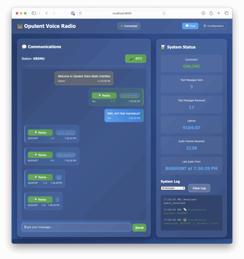
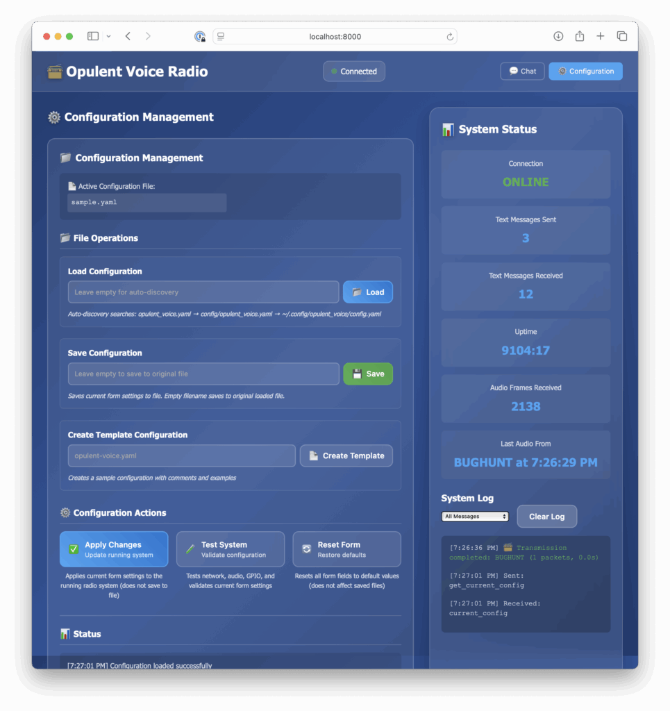
The web interface is available at http://localhost:8000 on the device running interlocutor.py.
Interlocutor features a modern glassmorphism-styled web interface for operation and complete system configuration. All configuration items are available at the command line or in the web interface.
The purpose of the Configuration System is to create, validate, and save one or more configuration files so that an operator can start the radio in a fully defined state.
Operational Modes
First, let’s talk about the command line interface (CLI) mode. This offers traditional terminal-based operation with full keyboard chat capabilities.
The simplest way to invoke this mode is by typing:
python3 interlocutor.py YOUR_CALLSIGN
In CLI mode, real-time voice transmission is done with a hardware PTT button. There is a keyboard chat interface. Voice has priority, with control messages second highest priority, and keyboard chat third. Debug output and system status are shown as text on the screen.
Second, let’s explore the web interface mode. The web interface is a modern browser-based interface with visual controls.
It is invoked by adding the –web-interface argument to program start. python3 interlocutor.py YOUR_CALLSIGN --web-interface
We find a detailed configuration management in Configuration tab, live status indicators, and real-time voice transmission with PTT control available in three different ways. First, as a hardware switch on designated GPIOs. Second, as a clickable button in the web interface. Third, the space bar when the message entry box does not have focus. Web interface has keyboard chat and shows system log, notifications for important events, debug output, and system status. Sent and received audio can be replayed from the message history window.
Dual-Mode Operation
Both interfaces can run simultaneously, providing flexibility for different operational scenarios or preferences. There are instant updates between command line and web interfaces via WebSocket communication.
Protocol and Network Configuration
Interlocutor implements the Opulent Voice protocol with sophisticated frame management. Here are the frame types and priorities.
2. CONTROL (Priority 2): PTT state changes, high priority queue, A5 messages
3. TEXT (Priority 3): Keyboard chat, normal priority queue
4. DATA (Priority 4): File transfers, low priority queue
External Network Ports:
57372: Network Transmitter port (configurable, connects to radio hardware, computer, or repeater). This is the only port you have to configure.
Internal Protocol Ports:
57373: Audio frames
57374: Text frames
57375: Control frames
These ports tell the receiver what kind of information it’s receiving. These ports are in the UDP header in each Opulent Voice frame. The protocol is extendable. Future data types get the next port available.
All frames follow the Opulent Voice protocol format. Opulent Voice Header: 12 bytes (sync word + station ID + type + sequence + length + reserved)
Payload: 122 bytes of data loaded up in 40 ms frames
GPIO Button: Physical button connected to Raspberry Pi GPIO
Web PTT: Additional click/touch controls in web interface. There’s a PTT button and the space bar activates PTT when the message entry box is not highlighted (does not have focus).
Audio Processing Pipeline:
1. Microphone input to PyAudio capture
2. Audio validation
3. Opus encoding (40ms frames, 16,000 bps bitrate)
4. Hardware audio callback
5. RTP header addition
6. UDP header addition
7. IP header addition
8. COBS encoding
9. Opulent Voice header addition
10. Network transmission
Chat Integration
Voice transmission has absolute priority. Text messages typed during PTT are buffered. Buffered messages transmit immediately when PTT releases. Control messages maintain high priority for system functions
Chat Modes:
Voice + Chat: Normal operation with seamless integration. Operators can choose voice or text as appropriate. This is the default mode.
Chat Only Mode: Keyboard-to-keyboard communication (similar to RTTY). This is set up with a command line argument --chat-only
Automatic Reconnection System
Interlocutor implements intelligent reconnection logic for the web interface.
Code contributions welcome via GitHub pull requests and filing issues. Documentation improvements welcome and encouraged. Testing and feedback valuable for development. Hardware testing on different platforms welcome and encouraged!
The system is actively developed open-source software, and features will evolve. Check the project repository for the latest updates and documentation.
But Wait, There’s More
Opulent Voice Demonstration Conference Server Beta Test Now Open
This project is called Locus, and the repository link, with manual and installation instructions, can be found here:
Key components of a fully implemented conference server (Opulent Voice repeater) are outlined below.
1. FDMA Uplink Channels Received at Spacecraft or Terrestrial Repeater
Multiple receivers monitoring different frequency slots simultaneously, each capable of demodulating and decoding the Opulent Voice protocol.
2. Conference Management Hardware and Software
This manages how stations can connect with other stations by maintaining lists of rooms or conferences. Conferences are logical groupings of stations.
3. DVB-S2 Downlink Multiplexer
This component takes all the conference data and creates a single high-bandwidth downlink stream.
Software modifications to Interlocutor, the human-radio interface for Opulent Voice stations, have been made in order to realize a simple repeater system. The Interlocutor repository can be found here:
By targeting the IP address of opulent.openresearch.institute, anyone running Interlocutor can participate on ORI’s demonstration conference repeater. This repeater is internet-only at the moment, but will have RF hardware in the next phase of work.
To configure Interlocutor for the conference server, here is an example invocation.
This sets up a station with ID QUARTER, running a web interface at 127.0.0.1:8000, and sends frames to opulent.openresearch.institute.
The next phase of work is to set up named conference rooms so that people can join based on event, subject matter, scheduled meetups, and other searchable categories. There will be a Conferences tab in the Interlocutor web interface that will populate whenever conferences metadata is received.
Key Features Unlocked in the Next Phase
Multiple simultaneous conversations are possible. Instead of traditional “one-at-a-time” repeater operation, users will have multiple conferences running simultaneously. A local weather net, an emergency coordinator channel, and a tech Q&A room are all active at once. Each of the voice transmissions and chat messages appear in the message history window of Interlocutor. The voice transmissions and chat messages are filtered by the receiving station based on the conferences from which the transmissions originated from.
Operators will browse active conferences and see things like participant counts, last activity, and have the ability to freely monitor any conferences.
Conference participation is straightforward. Operators have their station join a conference by transmitting in one. At that point, the station ID appears in the conference membership list. Before transmission to a Conference, the station ID would not appear in the list.
Conference lists are kept clean. Over time, a station ID that has joined a conference expires and is dropped off the list of stations in the conference. This is done after some configurable period of inactivity. The default in Locus is one hour. Conferences themselves, without active transmissions, can expire after some amount of time as well. This “time out” process emphasizes active conferences, reducing the amount of “empty rooms” that an operator would have to search through to find someone to communicate with.
Technical Implementation Strategy
Within Interlocutor, current conference server operation is essentially the same as if it was connecting directly to another station. If the target IP address is a conference server, then voice and text appear in the message history from all the stations that are transmitting. The Locus demonstration station at ORI simply forwards frames received. It has essentially one conference. This will change in the next phase. Current work is to continuously improve performance and user experience with the basic functions. Adding additional conference functions will follow shortly.
For this next phase, Interlocutor will have a third Conference Tab in the web interface. This will allow conference discovery and enable full participation. The banner on the Communications Tab will change to show when a server is connected, as opposed to a single directly connected station. This will be unobtrusive but clear.
We need to implement the frequency division multiple access (FDMA) receiver that manages multiple frequency slots on the uplink, and build the DVB-S2 Multiplexer for the downlink aggregation. Hardware for our open source HEO/GEO satellite project Haifuraiya has been demonstrated in the past, and these designs will be used for this project as well.
Discoverability Improves Engagement
In order to take advantage of the conference functions, individual stations use the Interlocutor program in essentially the same way as they would in a point-to-point contact. A fully implemented conference server will broadcast messages to be detected by Interlocutor receiver. These broadcasts list the conferences and the participants. Then, the web interface populates with the available conferences and exposes the controls for starting a new conference, joining an existing conference, or monitoring any conference. Operators join conferences by participating with a transmission. The repeater handles the complexity. The broadcast will be sent at the lowest priority level (data), as to not interfere with voice, text, or control frames.
The concept of conferences is central to the repeater experience. People playing a D&D game over the air would be in a game conference. That conference might be called “The Elven Empire”. People coming and going during drive time might join “I-15 Rollout”. An individual calling another individual for a one-on-one QSO would be in a conference too, which might be called “Ken’s Coffee Break” or “Everyone Welcome”.
Conferences become the fundamental organizing principle. This organizing principal shifts amateur radio from “everyone talks to everyone on one frequency” to “purposeful gatherings with context and discoverability.”
Traditional repeaters are like having one conference room where everyone shows up, takes turns to talk, and if you miss a transmission then that is just too bad. You missed it.
A conference-based system creates purposeful spaces. The D&D group doesn’t interfere with the emergency coordinators, and both can run simultaneously. If you missed a message, you can scroll up in the message history window. You can replay past audio transmissions from the UI Audio Bubbles or read the past chat message history. Both are in the message history window. Empty conferences time out and are removed, so that it doesn’t look like a ghost town or give a false sense of activity.
Instead of “I hope someone interesting is on the repeater,” users can browse conferences in the past, present, and future. A list of past conferences, out to some point in the past, can be maintained to show the frequency and type of activity. Any conference can be monitored. Current conferences are joined by transmitting in the conference. Future conferences can be listed in a schedule. This is like the difference between wandering into a random tavern hoping for good company versus checking a bulletin board that says “Adventuring Party Seeking Ranger Meet by the Old Oak” or “Storytelling by the Fire in the Great Hall.” This type of radio experience has natural social dynamics.
An operator can make a casual discovery and meet new friend.
“Oh, there’s a Python programming discussion with 4 people – that sounds interesting!”
Operators can make and advertise planned events.
“Tech Book Club session every Tuesday at 7 PM – join us!
Emergency coordination can be greatly improved. Operators can quickly and easily create dedicated emergency conferences during disasters. With authentication and authorization functions, these conferences can be limited to people that have, for example, completed specific training. A system like this can provide realistic emergency training opportunities that do not interfere with normal operation. Mentoring conferences can be set up to provide friendly and welcoming alternatives for education and learning.
The conference server manages conference data. A goal is to keep this to the minimal required state. The conference server doesn’t decide who can listen to what, unless there is an authentication and authorization policy in place from the repeater owner.
Use Cases
Opulent Voice naturally scales up. Here are some anticipated use cases. This is not intended to be a comprehensive list.
Simple Point-to-Point: Two or more people communicating point-to-point create the equivalent of a single conference. Whether the station is operating point-to-point or in a conference at a repeater, the program behaves almost identically. The only difference on the Communications tab is the heading color and title.
Local Repeater: Multiple conferences on one repeater system that is running a conference server.
Regional Network: Conferences can span multiple repeaters.
Satellite Integration: HEO satellites carry conference multiplexes to different continents
Internet Bridging: Conferences can include remote participants via internet gateways
The conference concept transforms amateur radio from “broadcast to everyone in range” to “purposeful communities of interest.” Conference discovery/joining is a different mental mode than active communication. Therefore, it gets a separate tab in the Interlocutor web interface.
Three-Tab Architecture Defined
Tab 1: Communications “I’m having a conversation” We keep the current design We use current message history and audio playback Active conference indicator at the top: “Currently in: Morning Coffee Chat (4 people)” Quick leave/switch button – minimal, non-intrusive Focus stays on the actual conversations
Tab 2: Conferences “I’m choosing who to talk to” New design to be implemented in the very near future Conference browser and discovery Create new conferences Join/schedule conferences Personal conference history and favorites Block lists
Tab 3: Configuration “I’m setting up my radio” We keep the current design Configuration Tab moves from position 2 to position 3 New conference configuration items Radio and system settings
Operator Mental Models
This creates a clear progression in the operator’s mind:
1) “I want to join a conversation” Check conference server status 2) If connected browse and join conferences 3) If no conferences appeal then “I can still talk directly to someone”
The central idea behind the conference tab is the transition experience: User browses conferences, finds “Python Coding Discussion (3 people)“, clicks join, gets smoothly transitioned back to their familiar communications interface, but now they’re talking with Python enthusiasts instead of whoever happened to be on the repeater.
Conference Servers feel like choosing your conversation rather than hoping for a good one.
Expect conference functionality to increase at the internet demonstration station over the next few months.
Open Research Institute Sphere of Activity
August, September, October 2025
5 August 2025 – Final Technological Advisory Council meeting at the US Federal Communications Commission (FCC) in Washington, DC. The current charter concludes 5 September 2025.
7-10 August 2025 – DEFCON 33 in Las Vegas, Nevada, USA. ORI plans an Open Source Digital Radio exhibit in RF Village, which is hosted by Radio Frequency Hackers Sanctuary.
10 August 2025 – Submission deadline for Open Source Cubesat Workshop, to be held 25–26 October 2025. Location is Serafio of the Municipality of Athens, Greece. Submission status !!!AI
1 September 2025 Our Complex Modulation Math article will be published in ARRL’s QEX magazine in the September/October issue.
5 September 2025 – Charter for the current Technological Advisory Council of the US Federal Communications Commission concludes.
19-21 September 2025 – ESA and AMSAT-DL workshop in Bochum, Germany.
25-26 October 2025 – Open Source Cubesat Workshop, Athens, Greece.
Thank you to all who support our work! We certainly couldn’t do it without you.
Four amateur radio operators (Alice, Bob, Carol, and Dave) are setting up 10 GHz microwave links. Each has a different antenna polarization: Horizontal, Vertical, Right-Hand Circular (RHC), and Left-Hand Circular (LHC).
Polarization Loss Rules
Same polarization: 0 dB loss
Cross-polarized linear (H vs V): 20+ dB loss
Circular to linear: 3 dB loss (either direction)
Opposite circular (RHC vs LHC): 20+ dB loss
The Clues
1. Alice can communicate with Bob with perfect signal strength (0 dB loss).
2. Alice gets terrible reception from Carol (20+ dB loss).
3. Alice receives Dave’s signal at reduced power (3 dB loss).
4. Bob can barely hear Carol (20+ dB loss).
5. Bob gets a good but reduced signal from Dave (3 dB loss).
6. Carol receives Dave’s signal at reduced power (3 dB loss).
7. One operator forgot to rotate their new IC-905 dish from its factory vertical polarization setting.
8. Bob notices that a 10 degree rotation resulted in a lot of signal loss.
Who has which antenna polarization?
Solution:
Alice: Horizontal
Bob: Horizontal
Carol: Vertical (IC-905 factory setting – forgot to rotate!)
Dave: Right-Hand Circular (RHCP)
From clue 1, Alice and Bob have 0 dB loss, therefore they have identical polarization.
From clues 2 & 4, both Alice and Bob get 20+ dB loss from Carol, so Carol has the orthogonal polarization to Alice/Bob. This 20+ dB loss could happen in two scenarios:
1. Alice/Bob are one linear polarization (for example, Horizontal), Carol is the orthogonal linear (for example, Vertical).
2. Alice/Bob are one circular polarization (for example, RHCP), Carol is the opposite circular (for example, LHCP).
From Clue 8, Bob has either vertical or horizontal polarization, as rotating the antenna results in noticeable loss. Rotating a circular polarized antenna doesn’t result in much loss.
From clues 3, 5, & 6, Dave gets 3 dB loss from Alice, Bob, and Carol. Since 3 dB loss occurs between circular and linear polarizations, and we suspect Bob is linear, then Dave must be circular.
Dave can get 3 dB from all three is if Alice/Bob/Carol are all linear polarizations, and Dave is circular.
Then clue 7 (IC-905 vertical) helps us determine which linear polarizations they have.
From clue 7, someone has an IC-905 in vertical polarization. This some “one” must be Carol (since she’s orthogonal to Alice/Bob). Only one operator forgot to rotate, so it can’t be both Alice and Bob with vertical.
Therefore: Carol = Vertical,
Alice/Bob = Horizontal.
Since we have Horizontal (Alice/Bob), Vertical (Carol), and one circular (Dave), Dave must be either RHCP or LHCP. We are going to say RHCP, but it is arbitrary. LHCP is correct too.
Congratulations to everyone who solved last month’s puzzle!
PUZZLE SOLVED! All 81 cells filled correctly with the 9 amateur radio bands!
160m
80m
40m
20m
15m
10m
6m
2m
70cm
70cm
20m
15m
6m
2m
40m
80m
160m
10m
6m
10m
2m
80m
70cm
160m
20m
40m
15m
80m
40m
160m
15m
10m
6m
70cm
20m
2m
20m
6m
10m
70cm
2m
15m
40m
80m
160m
2m
15m
70cm
40m
160m
80m
10m
6m
20m
10m
70cm
6m
160m
80m
20m
2m
15m
40m
15m
160m
20m
2m
6m
70cm
40m
10m
80m
40m
2m
80m
10m
20m
15m
160m
70cm
6m
Solution Key
80m
Original clues from puzzle
40m
Solved cells
27Given Clues
54Cells to Solve
9Amateur Bands
How Did You Do?
If you solved this puzzle, congratulations! You’ve mastered the amateur radio bands from 160 meters down to 70 centimeters. Look for next month’s puzzle challenge in the upcoming ORI newsletter!
Fill each row, column, and 3×3 box with all 9 amateur bands
Rules: Each row, column, and 3×3 box must contain exactly one of each amateur radio band (160m through 70cm). Blue cells contain given clues to help you solve the puzzle.
____
80m
____
____
15m
____
____
2m
____
____
____
15m
____
____
40m
____
____
10m
6m
____
____
80m
____
____
20m
____
____
____
40m
____
____
10m
____
____
20m
____
20m
____
____
____
2m
____
____
____
160m
____
15m
____
____
____
80m
____
6m
____
____
____
6m
____
80m
____
2m
____
____
15m
____
____
2m
____
____
____
10m
____
____
2m
80m
____
____
15m
____
____
6m
Amateur Radio Bands
160m
160 meters
1.8 MHz (Top Band)
80m
80 meters
3.5 MHz
40m
40 meters
7 MHz
20m
20 meters
14 MHz (DX Band)
15m
15 meters
21 MHz
10m
10 meters
28 MHz
6m
6 meters
50 MHz (Magic Band)
2m
2 meters
144 MHz
70cm
70 centimeters
420 MHz
Solution Next Month!
The solution to this Amateur Radio Band Sudoku will be published in next month’s ORI newsletter. Good luck solving it!