All the articles from the March 2026 Inner Circle Newsletter in one place.
The Case of the Missing Transmit Power
How a 4-bit Misalignment Stole 24 dB from the Opulent Voice Modem
The Opulent Voice modem for the LibreSDR graduated from the lab to the field in late March 2026. Instead of coaxial cables connecting transmitter to receiver, and receiver to transmitter, we now connected our brave little radios to filters and outdoor antennas.
And, nothing was received. The signal levels appeared to be very low. Even moving the antennas right next to each other resulted in only a few scattered frames demodulated and decoded.
Obviously, we needed an amplifier. Fortunately, we had plenty in stock from collaborating with University of Puerto Rico’s RockSatX team. They used an earlier version of Opulent Voice on their sounding rocket.
From the original listing at https://www.ebay.com/itm/363233702995
————————————————— Microwave RF Power Amplifier Board SBB5089+SHF0589 40MHz-1.2GHz Gain 25DB 10PCS
Specifications:
– Input voltage: 10~30V DC – Input power: about 5W – Working frequency: 40MHz~1.2GHz (0.04~1.2GHz) – Gain: about 25dB (may be higher) – Power: 2W (may be higher)
Attention:
We measured 80.7% ultra-high efficiency in tests, and the official chip manual also mentioned that there is more than 50% efficiency at P1dB. Overall, this SBB5089+SHF0589 is better than SBB5089+SHF0289. —————————————————
On 24 March 2026, we selected one of the amplifiers at random in order to characterize it in ORI’s Remote Labs. We connected the input of the amplifier to the output of the DSG821A signal generator. The signal generator was set to 431 MHz, which was the frequency we wanted to use. We connected the output of the amplifier through a 6 dB attenuator to the Rigol RSA5065N Spectrum Analyzer. We fitted a JST-HX power cable to the power connector of the amplifier. We provided 12 volts of power from the DP832 lab power supply.
The amplifier made 27 dB of gain from -100 dBm input to about -3 dBm input, made 20 dB at 0 dBm input, and worked pretty well up to 9 dBm input.
The next test was to remove the signal generator and connect a LibreSDR running Opulent Voice. Instead of a carrier wave from the signal generator we’d be sending an 81 kHz wide minimum shift key (MSK) signal from a real modem through the amplifier. We were intending to repeat the measurements we’d made with the signal generator. However, we noticed something very interesting. The signal level from the LibreSDR was expected to be about 0 dBm, which would provide enough drive to the amplifier to create enough gain to help our over-the-air tests succeed. However, when the LibreSDR, running Locutus and Dialogus, was commanded to transmit with PTT and audio frames from Interlocutor, the peak of the main lobe of the MSK signal was at 1 microwatt. If this was the true power output of the LibreSDR, then no wonder the over-the-air tests had failed.
The transmit power hardware attenuation setting was confirmed to be at 0 dB. This is set through an Industrial Input and Output (IIO) library attribute call, was correctly reported, and we saw that changing the attribute caused the signal to increase or decrease by the exact amount of gain. So, it wasn’t a configuration error. As far as the hardware was concerned, it was transmitting at 0 dBm.
The other possibility was that the I and Q signals were not being generated for transmit at full scale. If we weren’t filling up the registers correctly, then maybe we were accidentally dividing our signal down before it got to the antenna. Investigation turned to the Hardware Descriptive Language (HDL) files.
The Opulent Voice VHDL language modem, called Locutus, runs inside the LibreSDR FPGA. Data frames arrive via direct memory access, pass through the Opulent Voice frame encoder, are convolutionally encoded (K=7, rate 1/2), go through a byte-to-bit deserializer, and the resulting bits are sent to the MSK modulator. The modulator produces the I and Q samples that drive the AD9363 digital to analog converter (DAC). Software in the general purpose processor of the LibreSDR configures the IIO context and controls PTT.
The direct memory access transfers protocol data frames into the LibreSDR, and not IQ samples. So, the classic PlutoSDR bug of 12-bit samples being miscounted in a 16-bit word did not apply here. The modulator itself generates all I and Q waveforms. The frequencies are set by Dialogus at startup.
The Integrated Logic Analyzer (ILA) in the bitstream already had probes on two very important signals, tx_i_sync and tx_q_sync. These signals were measured right at the point where the samples enter the AD9361 core. A January 2026 ILA capture told the story clearly. The waveform showed clean MSK signals. No corruption, no skips, and with the exact right relationship to each other. At the time, this was a big milestone and part of the process of troubleshooting the porting of the HDL code from the PlutoSDR to the LibreSDR. But we’d overlooked something critical. The bug was right there in an otherwise perfect image.
The peak values of the I and Q waveforms were only plus and minus 1100 or so, in a 16-bit signed word. At first glance, a value of 1100 in a 16-bit word might not raise any red flags. The alarm bells ring when you know how the axi_ad9361 core actually reads those 16 bits.
There are two different conventions on the same bus. The axi_ad9361 core uses 16-bit data buses internally. However, the AD9361 and AD9363 (the chips used in these software-defined radios) have only 12-bit digital to analog converters. The documented convention, confirmed by a tour through Analog Devices Engineer Zone forum, is as follows.
RX (ADC Output) is 12-bit value in [11:0], sign extended to [15:12] TX (DAC Output) is 12-bit value expected in [15:4], which is the top 12 bits
In plain English, RX gives you the data right-justified. TX expects it left-justified. These are opposite conventions on the same 16-bit bus, and the apply whether the interface is CMOS (PlutoSDR) or LVDS (LibreSDR).
Our code, from msk_modulator.vhd, in the carrier_mod_proc section looks like this.
s1s and s2s are each signed 12-bit values from the numerically controlled oscillator (NCO). The lookup table fills using the command
ROUND(SIN(theta) * 1024.0)
which gives a peak value of plus or minus 1024. VHDL addition of two such values produces a 12-bit result that ranges from -2048 to +2048. So far so good. The resize call then sign-extends that 13-bit result into 16 bits. This is a right-justified 16-bit word, which is the opposite of what the Analog Devices core expects.
The full chain of what happens to the signal amplitude can be calculated.
The lookup table output is [11:0] signed and is a 12-bit sinusoid. s1s + s2s is [12:0] signed and is a 13-bit sum. Resize(…, 16) [15:13] sign extension with [12:0] as the data. This is right-justified. Analog Devices chip reads transmit values as [15:4], sending the top 12 bits to the DAC. Analog Devices reads [15:4], we drive [12:0], and this is a divide by 16 to the amplitude.
What’s the damage? -24 dB.
Why did this work in the PlutoSDR? Well, it didn’t. It did not produce full power, either. The same modulator code drove the Pluto variant of Opulent Voice. The -24 dB bug was there too. Why did we not notice it? We never graduated to over-the-air tests with the PlutoSDR. All of the tests transmissions were in the lab and were either conducted through coaxial cables or done with Vivaldi lab antennas right next to each other on the bench. With conducted tests, everything worked perfectly.
For ORI’s LibreSDR work, we were now in the field. We wanted to characterize the modem output before adding an amplifier. That scrutiny revealed the long-lived bug in the HDL.
Matthew Wishek NB0X implemented a fix on the tx_sample_scale branch of the published repository, with changes to two submodules, the NCO and the msk_modulator. No changes to the block design TCL or to msk_top.vhd were required.
In the NCO (sin_cos_lut.vhd), a new constant was introduced: CONSTANT FULL_SCALE : INTEGER := 2**(SINUSOID_W-1) -1. And, the lookup table fill function was changed from the hardcoded 1024.0 to * real(FULL_SCALE). With SINUSOID_W = 12, this gives FULL_SCALE = 2047, filling the entire signed 12-bit range. The fix is fully generic. It works for any value of SINUSOID_W.
In the modulator (msk_modulator.vhd), a new 3-bit input port tx_shift : IN std_logic_vector(2 DOWNTO 0) was added. The IQ output assignment was changed from a plain resize() to a shift_left() whose amount is driven by tx_shift at runtime.
The full 12-bit scale was achieved. With the sum now peaking at plus or minus 4094, left-shifting by 3 puts the signal in the correct place, which is [15:3]. The Analog Devices core reads [15:4], which is the full DAC scale. Making tx_shift a configurable port rather than a hardcoded constant is an elegant touch. Dialogus sets it through the register map at runtime, with no bitstream rebuild needed.
With the tx_sample_scale fix integrated and a new bitstream loaded, the Opulent Voice modem then achieved its first successful over the air transmission. This was from one building to another, with the full signal chain, from a LibreSDR to another LibreSDR. Voice traffic and text messages were received, with excellent audio quality. The ~30 dB shortfall that had been quietly sitting in the hardware since the original modulator was gone.
Lessons Learned
RX and TX use opposite justify directions in axi_ad9361. This is documented, but really only in a so-called Verified Answer on Analog Devices Engineer Zone forum. It’s not prominently documented in the IP wiki. The wiki describes the 16-bit data base and mentions that the IP “always works in 16 bits”, but does not call out the left/right justification asymmetry in a way that is easy to find. If you are writing custom HDL that drives DACs, then you should read the forum thread at https://ez.analog.com/fpga/f/q-a/112155/axi_ad9361-data-format
ILA probes are worth their cost. The screenshot from the ILA capture back in January 2026 told us the answer, if we had known what the question was. Running ILA and keeping the results pays off because you can go back and look at signals that may not be accessible otherwise. Wire up ILA early and often and be curious about your signals. Go for a tour. Explore your design and the design of any infrastructure that you are working with.
-24 dB is a recognizable signature. In fact, any multiple of -6 dB is significant. Each bit of DAC resolution is 6 dB, so if you’re missing something like 24 dB, then an inadvertent four-bit shift might be the culprit.
Fix things at the right layer. The initial discussions included assumptions such as “the fix should live in the block design TCL file” or maybe in msk_top. Matthew chose to fix it inside the modulator and NCO submodules. This is the better choice. It makes the modules self-consistent, removes the need for platform-specific fancy workarounds or settings, and ensures that any future target automatically benefits. When a submodule’s output format is wrong, fix the submodule rather than papering over it at the integration layer.
Acknowledgements
The modulator and NCO were written by Matthew Wishek NB0X, whose clean modular architecture made the bug straightforward to trace, and whose tx_sample_scale branch fix resolved it elegantly at the right layer. Thanks to the ADI FPGA team (Laszlo) for the EngineerZone Verified Answer that became our primary citation. Thanks to Paul KB5MU and Michelle W5NYV for working through this signal chain, characterizing the amplifier, and methodically testing the new firmware.
February 2026 Storm Takes Down Communications Infrastructure on Mount Laguna, CA, USA
by Sudoku Ham for ORI
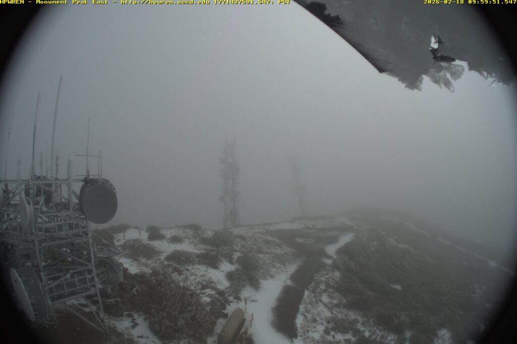
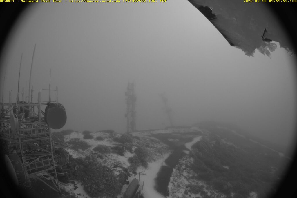
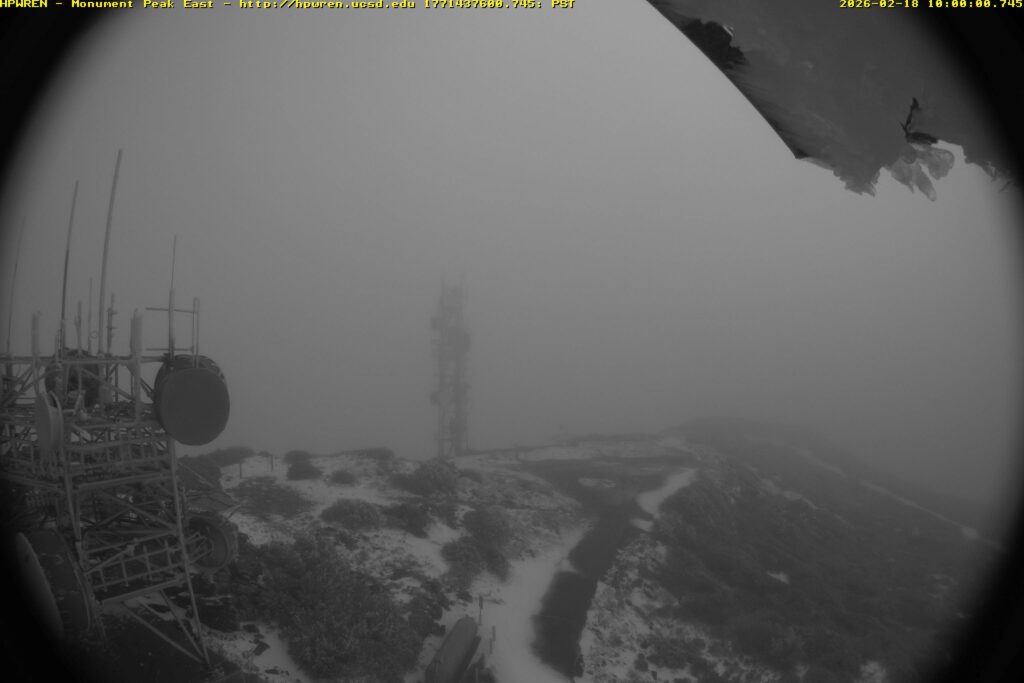
At exactly 10:00 AM on Wednesday, February 18, 2026, a communications tower on Monument Peak in the Laguna Mountains was blown over during a powerful wind event, captured in real time by a nearby wildfire camera system. The tower, owned by American Tower Corporation (ATC), had been carrying an AT&T cellular site and several microwave hops. According to sources familiar with the site, that was the only functional equipment on the structure at the time of its collapse.
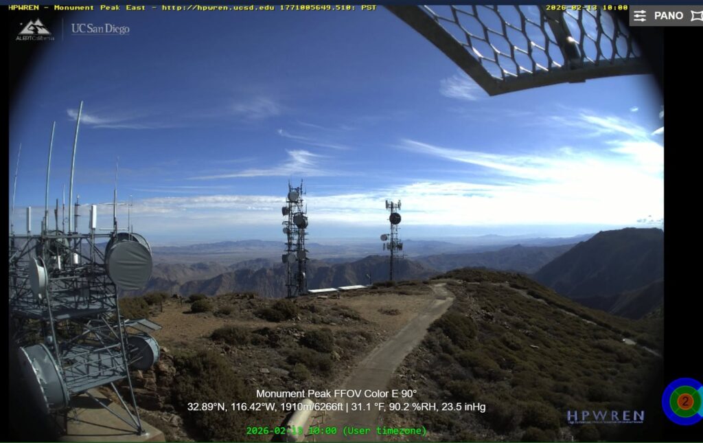
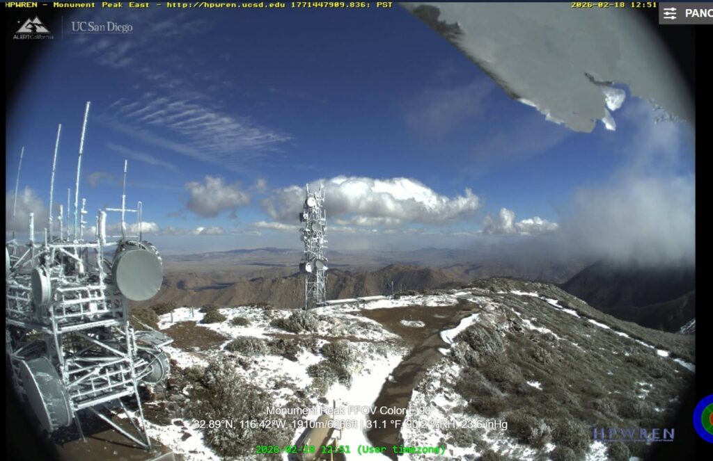
The failure was documented by the HPWREN (High Performance Wireless Research and Education Network) camera system. This system is operated by UC San Diego’s San Diego Supercomputer Center. Video assembled from the east-facing fixed-field-of-view camera shows a major wind event immediately preceding the collapse, with the tower going over at 10:00 AM. A before-and-after comparison of HPWREN still frames, one from February 13 showing the tower standing, another from later on February 18 showing it gone, confirms the loss. Snow visible in the post-collapse image and on the wreckage is consistent with the heavy winter weather that preceded the failure.
Hans-Werner Braun, Research Scientist Emeritus at UCSD, provided additional HPWREN images. Hans-Werner is deeply involved with HPWREN, having served as Principal Investigator. “These are from the 10 second data that we additionally collect for a small subset of the cameras.”
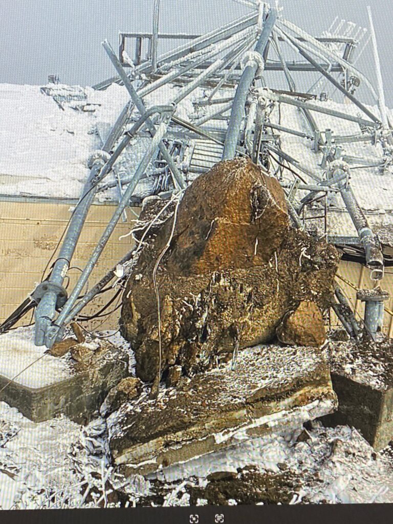
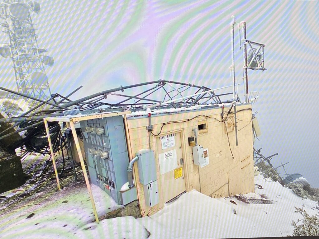
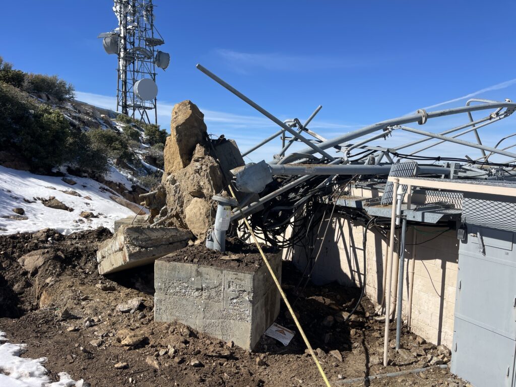
Damage photos obtained from CORA (Cactus Open Repeater Association) members, originally shared by Chris Baldwin, show the aftermath in stark detail. A lattice tower structure torn from its concrete foundation, the base ripped out of the ground with rebar exposed, and the wreckage draped across an equipment shelter labeled “FACILITY 3.” The concrete pier appears to have failed catastrophically, with the entire foundation block uprooted rather than the tower buckling above the base. The combination of snow and ice loading on the structure, high sustained winds, and the age of the tower and presumed lack of recent maintenance all contributed to the failure.
Steve Hansen, W6QX, first drew attention to the HPWREN imagery showing the tower’s disappearance.
The Storm
The collapse occurred during a series of storms that struck San Diego County over the span of four days. The first wave hit Monday, February 16, bringing heavy rain and winds gusting to 60 mph on Mount Laguna. A second, more intense wave arrived overnight Tuesday into Wednesday, the morning the tower fell. That wave produced winds of 80 mph at El Cajon Mountain, measured at 3:30 AM. Wind was measured at 76 mph at Birch Hill in the San Diego County mountains, and at 52 mph in the desert. The National Weather Service reported snow accumulations approaching a foot on Mount Laguna, with additional snow bands continuing through February 19. A third and final round brought further showers and gusty winds on Thursday the 19th before conditions improved Friday.
The HPWREN camera overlay on the February 18 image recorded conditions at Monument Peak of 31.1°F, 90.2% relative humidity, and 23.6 inHg barometric pressure. It was cold, and the front had clearly moved through.
What Was on the Tower?
Monument Peak (32.89°N, 116.42°W, at 6,271 feet) sits at the eastern edge of the Laguna Mountain Recreation Area within the Cleveland National Forest. It is one of the most significant multi-use communications sites in eastern San Diego County, with a coverage footprint extending from the Salton Sea south to the Mexican border and west across the county.
The ATC tower that collapsed was one of multiple structures at the site. The site hosts a diverse set of users and systems. Services known to operate from Monument Peak include the following.
Amateur Radio: The East County Repeater Association (ECRA) operates several repeaters from the Monument Peak site, including 147.240 MHz (+ offset, PL 107.2 Hz. K6KTA, which is a joint effort with CORA that participates in the CalZona Link), 446.750 MHz (- offset, PL 107.2 Hz), and 449.180 MHz (- offset, PL 88.5 Hz). These repeaters appear to have been on a different structure than the one that fell. Operators are encouraged to confirm current status on the air.
HPWREN/ALERT: This system from UC San Diego operates fixed-field-of-view and pan-tilt-zoom wildfire detection cameras, microwave backbone links, and a weather sensor suite from the site. Monument Peak is a backbone node in the HPWREN network and has been since the project transitioned from nearby Stephenson Peak. The HPWREN cameras that documented this collapse were themselves mounted on a separate structure and survived.
NASA Space Geodesy: The Monument Peak compound hosts NASA’s MOBLAS-4 Satellite Laser Ranging (SLR) system, which has operated from this location since 1981, along with a GNSS antenna and an EarthScope seismic station.
Commercial and Public Safety: There are multiple microwave relay dishes and panel antennas visible in the HPWREN imagery on surviving structures. Historical records show San Diego County Sheriff’s Office VHF low-band repeater infrastructure at the site dating to the 1960s.
According to sources familiar with the site, the only functional equipment on the collapsed ATC tower was the AT&T cell site and its microwave backhaul links. The full inventory of what had previously been on the structure versus what was still active is not entirely clear, but the tower appears to have been underutilized at the time of its failure.
What We Know and What We Don’t
The video from the HPWREN cameras answers the biggest question. When did it fall? At 10:00 AM on February 18, during the second and most intense storm wave. Sources who have viewed the time-lapse describe it as showing a clear wind event immediately before the collapse. As is often the case with periodic camera captures of structural failures, the tower is there one frame and gone the next.
What was the failure mode? The damage photos show the concrete foundation pier uprooted from the ground rather than the tower folding at a structural joint. Whether ice loading, sustained wind, a gust event, or a combination caused the failure is unknown. No formal engineering assessment has been publicly released, but commenters seem surprised about the relatively small amount of concrete that was pulled up.
What services are currently offline? The ECRA repeaters and HPWREN systems appear to have survived on other structures. The primary loss appears to be AT&T cellular coverage and microwave backhaul from this site. Operators in the coverage area, particularly in eastern San Diego County and the Imperial Valley, may have noticed cellular outages.
What Happens Next
The central question is whether American Tower Corporation will rebuild. As one source familiar with the site put it (Chris KF6AJM), the only functional thing on the tower was the AT&T cell site with a few microwave hops. Whether that single-tenant revenue justifies the cost of constructing a new tower at a remote mountaintop location in a national forest, with all the permitting, environmental review, and logistics that entails, remains to be seen. It is not clear if that is profitable enough for ATC to put money into the site.
Mountaintop tower sites in places like the Cleveland National Forest are expensive to build and maintain. Access roads can be difficult in winter. Construction requires Forest Service approval. And the economics of a single-carrier site are thin compared to a multi-tenant tower in an urban area. There has been a long-term trend away from using large mountaintop towers, with capacity replaced by fiber backhaul and fixed wireless broadband. The reason for this is that wide coverage is now less valuable than capacity per user. Higher data rates per commercial cellular user cannot be delivered by one large site covering a large land mass as easily and cheaply as can be delivered with more sites all closer to the ground.
On the other hand, Monument Peak provides cellular coverage to areas of eastern San Diego County and the Imperial Valley that are otherwise difficult to serve. The microwave hops that ran through this tower may also have been part of a backhaul chain serving other sites. The downstream effects of this loss on AT&T’s network in the region are not yet clear.
Monument Peak has weathered storms before. HPWREN documented significant wind damage at their Big Black Mountain relay site in January 2018 during a Santa Ana event with 80-90 mph winds, and the HPWREN team rebuilt that site with an improved design to better withstand future weather. A similar assessment and improved rebuild process will likely be needed here for the commercial tower that fell if the economics support it.
For a site that serves as a critical node in the region’s wildfire detection network, amateur radio infrastructure, scientific instrumentation, and commercial communications, the loss of even one tower could have cascading effects. The coming weeks will tell us more about the extent of the damage, any additional as-yet undiscovered damage on other towers, and the timeline for restoration.
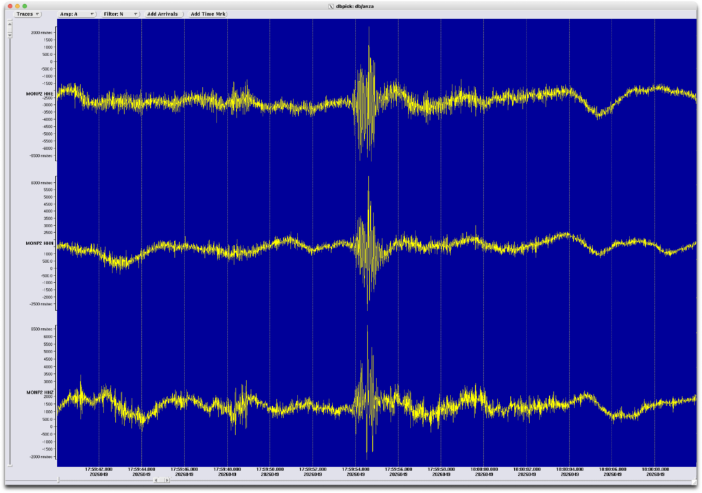
Dr. Frank Vernon, primary investigator for the HPWREN program, confirmed that no HPWREN assets were on the tower that fell. He added via email that UCSD has a seismic station 250 meters from the tower. “Looking at the seismic data”, Dr. Vernon explained, “it looks like we can see the tower hitting the ground.”
Timeline: 09:59:51.5 Color mobo shows tower tilting (see photo from Dr. Werner-Braun above) 09:59:52.1 Monochrome mobo shows tower tilting more (see photo from Dr. Werner-Braun above) 09:59:54 Seismic signal observed
James Davidson (UCSD) provided an additional damage photo, pointing out that “there isn’t much concrete below ‘grade’, and you can also see the rods sticking out, with a big chunk of rock pulled up too.”
If you have additional information about this event, particularly regarding which services are affected or the path forward for restoration, please contact us at ORI. Newsletter signup here: https://www.openresearch.institute/newsletter-subscription/
Photo Credits and Sources
Damage photos: Chris Baldwin, via CORA (Cactus Open Repeater Association) members, and James Davidson (UCSD).
HPWREN before/after camera images: HPWREN Monument Peak FFOV Color E 90° camera, UC San Diego / San Diego Supercomputer Center. HPWREN is funded by the National Science Foundation (Grant Numbers 0087344, 0426879, and 0944131). http://hpwren.ucsd.edu. HPWREN 10-second camera subset imagery from Hans-Werner Braun.
Tip on HPWREN imagery: Steve Hansen, W6QX.
Seismic chart: Dr. Frank Vernon.
Storm data: National Weather Service San Diego (NWS SGX); NBC 7 San Diego; San Diego Union-Tribune; KOGO Newsradio 600; ABC 10News San Diego.
Site information: American Tower Corporation; MRA-Raycom (mra-raycom.com); NASA Space Geodesy Project (space-geodesy.nasa.gov); ECRA (ecra-sd.com); RepeaterBook; N6ACE repeater listings.
Lunar Descent, the BSides San Diego 2026 RF Village Capture the Flag (CTF) from ORI
A capture-the-flag challenge based on a real signal processing problem in a radar altimeter!
Indian Space Research Organization (ISRO) designed a Ka band radar altimeter (KaRA) that guided Chandrayaan-3 to a soft lunar landing on 23 August 2023. The Radar Altimeter Processor (RAP) computes altitude and velocity from FMCW chirp signals, running on a single Xilinx Virtex-5 FPGA. This CTF uses a Python model of that system, faithful to the published paper in the Aeronautics and Electronic Systems Journal, where the altimeter feeds a landing autopilot. In our CTF, the altimeter works perfectly. The autopilot keeps crashing. Why? (solution in next newsletter!)
What did the participants see? A python script that could be installed on their computer and then run.
pip install numpy matplotlib
python lunar_descent_ctf.py --help        # See all options
python lunar_descent_ctf.py               # Run the mission, watch it crash
python lunar_descent_ctf.py --modes       # See the sweep mode table
python lunar_descent_ctf.py --test -p all # Test all three profiles
python lunar_descent_ctf.py --score       # Score your fix and earn flags
Rules
Edit ONLY the `MeasurementQualifier` class (clearly marked in the source)
Don’t change the RAP, signal generation, autopilot, or scoring
The qualifier decides what the autopilot sees — fix it there
Submit flags at the RF Village table
Three Flags
None of the flags are “free”. The buggy code scores 0 / 1000 points out of the box.
Flag
Points
Challenge
RECON
100
Explain the bug to RF Village staff. No hash on screen.
FIRST LIGHT
500
Land all three profiles without crashing.
NO GAPS
400
Zero qualifier rejections on all three profiles.
Total: 1000 points
The Scenario
The radar altimeter was tested on helicopters and aircraft at altitudes above 50 meters. It worked flawlessly. Field test performance met all mission specifications.
The altimeter is now integrated with a landing autopilot that uses both altitude and velocity measurements for thrust control during final approach. In simulation, the autopilot crashes the lander every time below 15 meters altitude. The altitude readings are fine. Sub-meter accuracy all the way to touchdown. Something else is killing the lander.
You need to find out what’s going wrong and fix the measurement qualification logic so the autopilot can land safely.
Difficulty Curve
0 points: Running the code unmodified. The default run shows OK status all the way down until the final approach, then CRASH.
100 points: Explaining the problem to staff.
600 points: Fixing the `MeasurementQualifier` so it can land.
1000 points: Eliminating all qualifier rejections.
Validating Flag 1 (RECON)
No hash is printed on screen for Flag 1. Staff issue the flag manually.
Timing
The CTF ran all day alongside the workshop modules and talks. It’s self-paced and doesn’t require staff attention except for Flag 1 validation and prize distribution.
Test Profiles
Profile
Character
What It Tests
standard
Chandrayaan-3-like smooth descent, 10 km → 3 m, with altitude excursion at 20 m (thruster anomaly or drifting over crater)
Landing
aggressive
Fast exponential braking, 10 km → 3 m in 400 s
Rapid mode transitions at hight altitude + Landing
stepwise
Hover at guard band boundaries (9851/4795/2334/553/131/31/5 m), drop between them
Mode transitions + Low Hover
The Physics
The RAP uses FMCW radar. Up-chirp and down-chirp signals produce beat frequencies:
Altitude comes from the sum: R = M × (f_up_index + f_dn_index). Velocity comes from the difference: fd = (f_dn_index − f_up_index) × freq_res / 2.
The FFT is always 8192 points, but the number of real signal samples depends on the sweep time:
Mode 12 (high altitude): 8192 samples, full FFT Mode 0 (3 m altitude): 14 samples, 99.8% zero-padding
Connection to Real Engineering
The problem is pedagogically framed but the pattern is real. Sensor qualification, knowing when to trust a measurement and when to reject it, is important.
Radar and sonar tracking systems (Doppler reliability vs integration time) GPS/INS integration (knowing when satellite geometry is too poor to trust) Medical imaging (SNR-dependent confidence in measurements) Autonomous vehicle sensor fusion (camera vs lidar vs radar confidence)
The paper mentions “three sample qualification logics to generate the final altitude” without detailing them. What are those logics? Will some of those qualification logics help solve this CTF?
Source
Based on: Sharma et al., “FPGA Implementation of a Hardware-Optimized Autonomous Real-Time Radar Altimeter Processor for Interplanetary Landing Missions,” IEEE A&E Systems Magazine, Vol. 41, No. 1, January 2026. DOI: 10.1109/MAES.2025.3595090
BSides San Diego 2026 RF Village Demonstrations
This is what development looks like!
Open Research Institute organized and executed the RF Village at BSides San Diego on 4 April 2026. This highly anticipated sold-out annual event has a focus on cybersecurity and DIY problem solving. Held at Montezuma Hall at San Diego State University, the one-day event had multiple speaking tracks, at least three Capture the Flag contests (CTFs), an electronic hackable badge, a variety of food and drink available throughout the day, extensive volunteer support, relevant and timely workshops, an After Hours party with more food and drink at Aztec Lanes bowling alley, and a vibrant Village Square that combined Villages and Vendors.
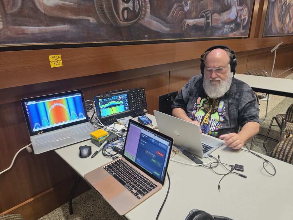
BSides San Diego 2026 RF Village Opulent Voice Development station staffed by Paul Williamson KB5MU. The post it note on the wall says “This is what development looks like!”
ORI served as the organizer for RF Village, bringing four staff members and multiple exhibits. We debuted our Lunar Lander CTF, announced the W6ORI amateur radio club, and gave away a large box of Amateur Satellite handbooks. We had RFBitBanger kits available for donation (5 were sold), hosted a live Meshcore node, and exhibited a real live FPGA development station with lab equipment for Opulent Voice. Our poster session included Authentication and Authorization and the technical side of RFBitBanger. Thank you to BSides San Diego for the excellent support, with rotating village volunteer staffers, volunteer green room, excellent communications before during and after the event, and genuine care for positive participant experience. Organizations like this make demonstrating open source digital radio work a real joy instead of a daunting chore.
Demonstrations give you deadlines, documentations, and get things “done”. The BSides Opulent Voice demonstration revealed some immediate problems with the 24 dB transmitter fix. The signal was clearly being transmitted at sufficient power, but the symbol and frame lock were not happening. We were seeing “garbage” frames where we were expecting to see actual live data.
Since the over-the-air voice call had worked so well just a few days prior, what was going on? The demonstration was still very successful, as plenty could be shown to the steady stream of people at the RF Village. As the day progressed, more information was gathered. It was very clear we’d have to go back to the lab to figure out how a badly needed transmitter fix had broken the receiver. Why was it working over the air, and not in RF loopback on the bench? First, we went back to the VHDL-only test bench. This sends 10 frames into the transmitter, routes the transmit I and Q streams right back to the receiver, and then demodulates, decodes, and displays the frames. The data in should match the data out. And, frames were coming out, but they were completely scrambled! Something had gone wrong in the RF loopback.
The difference between simulations and real life is usually a lot, and Opulent Voice is no different. A real hardware RF loopback has the radio chip in the loop. The VHDL test bench has only the FPGA contents. We don’t have analog to digital converters (ADCs), digital to analog converters (DACs), or anything else that is in the radio chip. Since the transmitter fix had a lot to do with how the transmitter DAC dealt with the data, it seemed reasonable to assume that the transmitter fix had upset the receiver.
The missing gain was in the transmitter, but the fix applied some math changes to both the transmiter and the receiver, and investigating this took up part of the next day back in the lab. WIth two minor changes, the test bench started working flawlessly again. A new version of the firmware was created, and… it didn’t work in hardware at all! Symbol lock and frame lock were totally non-functional. The plot had certainly thickened.
This is one of the many reasons why demonstrations are so valuable. We find things that we might not go looking for, and it forces us to regularly show things working end-to-end. Work continues this week in the lab to separate the transmitter fix from inadvetently affecting the receiver, and bring us back to working perfectly over the air as well as in simulation.
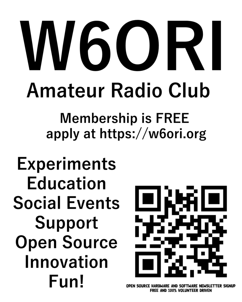
Open Research Institute granted Amateur Radio Club Call W6ORI
ORI now has its very own amateur radio club call. Membership in ORI’s amateur radio club is free. Just sign up for the Inner Circle Newsletter. Below is the poster announcing the debut of W6ORI. The announcement was made in RF Village at BSides San Diego, held at SDSU Montezuma Hall on 4 April 2026.
ORI Invited to Present Open Source Reference Design for IEEE P1954 UAV Communications Standard
Open Research Institute has been invited to present at the IEEE P1954 working group meeting on April 8th. Our topic: how to build an open source reference implementation for the emerging standard on self-organizing, spectrum-agile UAV communications.
What is IEEE P1954?
IEEE P1954 defines architecture and protocols that allow unmanned aerial vehicles to automatically form networks, dynamically access available spectrum, and coordinate communications without centralized infrastructure. Think of it as giving drones the ability to self-organize into mesh networks while intelligently sharing radio spectrum. These are critical capabilities for search and rescue, disaster response, infrastructure inspection, and beyond.
The standard is deliberately technology-agnostic. It specifies what UAV communication systems need to do, not how to build them. That’s where reference implementations come in.
Why Open Source Matters Here
Standards without working implementations remain academic exercises. An open source reference design serves multiple purposes
Experimentation platform: Researchers and developers can test ideas against a working baseline
Conformance validation: Implementers can verify their systems behave correctly
Lowered barriers: Smaller players can participate without building everything from scratch
Vendor neutrality: No single company controls the reference, aligning with the standard’s technology-agnostic philosophy
What ORI Brings to the Table
ORI’s existing work maps remarkably well onto P1954’s architecture. The standard envisions two distinct communication tiers:
Command & Control (C2): Safety-critical links requiring high reliability, low latency, and modest data rates
Payload: High-throughput channels for video and sensor data where best-effort delivery is acceptable
Our Opulent Voice protocol (MSK/CPFSK, constant envelope, narrowband) is designed for exactly the reliability-first requirements of C2 links. Our Neptune OFDM work addresses the high-throughput payload tier. Both have FPGA implementations in progress.
The standard also includes a SHALL-level requirement that UAVs “embed radio equipment such as software defined radios”. This is precisely our domain.
The Path Forward
We’re proposing to bring implementable chunks of P1954 into ORI repositories as open source FPGA and general-purpose processor designs. This isn’t about implementing the entire standard overnight. It’s about identifying the pieces most amenable to open source development and building momentum from there.
The April 16th meeting is our opportunity to discuss this approach with the working group and align our efforts with their priorities.
Get Involved
If you’re interested then this is an opportunity to contribute to an emerging international standard from the ground floor. Watch for updates on our mailing lists and repositories.
Welcome! DVB-S2 Receiver for Haifuraiya A Picture is Worth a Thousand Words Inner Circle Sphere of Activity Rolling Dice Over Radio Four Dice Bugs and a Microphone Upgrading a Hard-Decision Viterbi Decoder to Soft-Decision Retevis RT86, Hamcation Sponsorship, and 70cm Band Protection Is Amateur Radio an Alternative to Age-Restricted Social Media?
Welcome to the Debugging Issue!
It’s February 2026 and this issue of Inner Circle has a special focus on Debugging. How do you feel about this necessary and often frustrating process?
Open Research Institute is a non-profit dedicated to open source digital radio work on the amateur bands. We do both technical and regulatory work. Our designs are intended for both space and terrestrial deployment. We’re all volunteer and we work to use and protect the amateur radio bands. You can get involved by visiting https://openresearch.institute/getting-started
We equally value ethical behavior and over-the-air demonstrations of innovative and relevant open source solutions. We offer remotely accessible lab benches for microwave band radio hardware and software development. We host meetups and events at least once a week. Members come from around the world.
Calling All Adventurers: Help Us Complete the dvb_fpga Repository
Rolling for Initiative
Fellow adventurers of the amateur radio realm, we have a quest of legendary proportions before us. The dvb_fpga repository, Open Research Institute’s open-source FPGA implementation of DVB-S2 components, sits at a critical juncture. The transmitter side has been conquered, tested, and proven in battle. But the receiver? That’s the dragon’s lair we haven’t fully mapped yet.
We’ve built a magnificent ballista (the transmitter) that can launch messages into the sky with precision. But catching those messages when they come back? That requires a completely different set of skills. Timing, synchronization, error correction, and the arcane arts of signal processing.
The Story So Far: Our Transmitter Victory
The dvb_fpga repository at https://github.com/OpenResearchInstitute/dvb_fpga already has 130 stars and 39 forks. This is a testament to Suoto’s leadership and the community’s interest. The transmitter chain is complete. The Baseband Scrambler, BCH Encoder, LDPC Encoder, Bit Interleaver, Constellation Mapper, Physical Layer Framing have all been tested and hardware-verified
The entire transmitter chain synthesizes cleanly in Vivado for a Zynq UltraScale+ at 300 MHz, using only about 6.5k LUTs, 6.1k flip-flops, 20 block RAMs, and 64 DSP slices. It’s lean, mean, and ready for deployment. All outputs match GNU Radio reference implementations bit-for-bit.
The Dragon’s Lair: Building the Receiver
Here’s where the quest gets interesting. If the transmitter is like carefully packing a message into an enchanted bottle and throwing it into a stormy sea, the receiver is like trying to catch that bottle while blindfolded, in a hurricane, not knowing exactly when it will arrive—and then having to unscramble the message even if some of the ink got smeared.
The DVB-S2 receiver needs several major components, each a boss encounter in its own right:
Symbol Timing Recovery “The Temporal Synchronizer”
Our receiver clock and the transmitter clock are in different time zones, metaphorically speaking. They drift, they jitter, they disagree about the fundamental nature of time. Symbol timing recovery must analyze the received waveform and figure out exactly when to sample each symbol.
Frame Synchronization “The Beacons are Lit!”
DVB-S2 frames start with a 26-symbol Physical Layer Start of Frame (PLSOF) sequence. It’s like a lighthouse beacon in the rain and fog. The frame synchronizer must detect this pattern, lock onto it, and maintain frame alignment even as conditions change. Miss the beacon, and you’re lost at sea.
Carrier Recovery “The Phase Walker”
Frequency offsets and phase drift cause the received constellation to spin and wobble. Carrier recovery must track these impairments and correct them in real-time. It’s like merging into traffic on a busy freeway. You have to match the speed of the rest of the traffic in order to get where you want to go.
LDPC Decoder “The Error Slayer”
This is the final boss. Low-Density Parity Check (LDPC) codes have near-Shannon-limit error correction performance, but decoding them requires iterative belief propagation across massive sparse matrices. The DVB-S2 LDPC decoder must handle frame sizes up to 64,800 bits with various code rates. Implementations exist (Charles Brain’s GPU version, Ahmet Inan’s C version in GNU Radio), but we need an efficient, open-source FPGA implementation.
Adventurers Wanted: Your Skills Are Needed
This quest isn’t for a single hero. It’s for a party. We need diverse classes of contributors. We need FPGA Wizards, who are versed in VHDL or Verilog who can write synthesizable RTL. The existing codebase uses VUnit for testing. DSP Clerics are needed. These are signal processing experts who understand timing recovery algorithms, PLLs, and carrier synchronization techniques. Algorithm Bards, who can implement LDPC decoders (Min-Sum, layered architectures) and understand the mathematics of iterative decoding. We need GNU Radio Rangers, Python experts who can create reference implementations and test vectors. And, Documentation Warlocks, the Technical writers who can document architectures, interfaces, and usage in clear accessible language.
Your Starting Equipment
You don’t have to start from scratch. ORI provides Remote Labs, granting access to Xilinx development boards (including ZCU102 with ADRV9002 and a ZC706 with ADRV9009) and test equipment up to 6 GHz. Real hardware, remotely accessible. Existing test infrastructure is VUnit-based testbenches and GNU Radio data generation scripts. These are already in the repository. Reference implementations exist. GNU Radio’s gr-dvbs2rx and Ron Economos’s work provide software references to test against. And, we have community with an enforced code of conduct. The ORI Slack, regular video calls, and an international team of collaborators have built a friendly environment for people to build quality open source hardware, firmware, and software.
The Treasure at Journey’s End
Why does this matter? An open-source, FPGA-based DVB-S2/X receiver enables amateur satellite communications, including but not limited to Phase 4 Ground’s digital multiplexing transceiver for GEO/HEO missions. Students can learn real-world DSP implementations. Experimenters can modify and experiment without proprietary limitations. Commercial DVB-S2 receivers cost thousands of dollars and are black boxes. An open-source FPGA implementation changes the game entirely.
Join the Party
Ready to roll for initiative? Here’s some ways to get started. Fork the repository: github.com/OpenResearchInstitute/dvb_fpga Join ORI Slack: Request an invite at openresearch.institute/getting-started Check the issues: Seven open issues await eager contributors Request Remote Lab access: Real hardware for real testing Make your own Adventure: Start with symbol timing, frame sync, or dive into LDPC decoding
At Open Research Institute, we believe that open source approaches to digital communications yield the best outcomes for everyone. This project is living proof. The transmitter exists because volunteers made it happen. The receiver needs you.
May your synthesis always meet timing, and your simulations always match hardware!
A Picture is Worth a Thousand Words
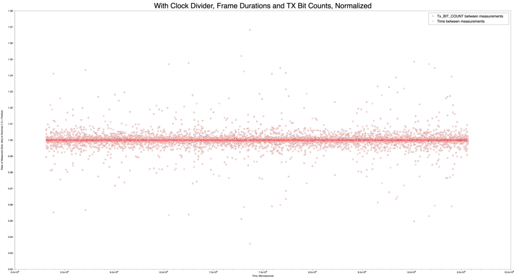
This image, made with the MacOS DataGraph program by Paul Williamson KB5MU, was created in order to answer a question about the LibreSDR integration effort. Are the frames really coming out at 40ms all the time, and at what rate is the modulator trying to accept bits during that time? Answers should be yes, and 2168 bits per frame. Here we’ve measured both the duration and the count of bits made available in an FPGA register, and normalized them both so that the nominal value is shown as 1.0. Black circles are bits, and red circles are durations. You’ll have to look closely to see that the red and black circles are paired up almost perfectly. There’s some variation in the duration measured by this method, but it is mostly synchronous with the bit count measurement. The variation shown here is only a few percent, though it looks a bit messy. This is a good result, showing that frame timing was preserved.
Quality instrumentation enables debugging.
Rolling Dice Over Radio: Games, Community, and an Extensible Command System for Interlocutor
Building a framework for shared activities on the Opulent Voice Protocol
Michelle Thompson, W5NYV
Drop into many repeater nets or tune across the bands and you may find the same small group of regulars having the same conversations. Newcomers often report that the airwaves don’t feel as welcoming as they should. That there’s no obvious reason to key up, nothing to do together, no shared activity that would give someone a reason to come back tomorrow. The technical barriers to entry have been falling for years, but some social ones seem to remain.
What if your radio could roll dice? What if a group of operators could play a tabletop role-playing game (RPG) campaign over a digital voice link, with the interface handling initiative rolls and ability checks right in the chat window? What if the same framework that rolls a d20 could also deal cards for poker night, flip coins for a bet, or run a trivia game? Suddenly there’s a reason to get on the air that has nothing to do with signal reports and everything to do with having fun together.
That’s the idea behind the new command system in Interlocutor, the human-radio interface for the Opulent Voice Protocol. We built an extensible slash-command architecture, starting with a Dungeons and Dragons (D&D) dice roller, that gives operators and developers a framework for creating shared activities over radio. This article describes the design, how it works, and how you can extend it.
Why Games Matter for Amateur Radio
Games are how humans build community. A weekly D&D campaign gives people a standing reason to show up. A card game creates natural turn-taking and conversation. Even something as simple as a shared dice roll creates a moment of anticipation and reaction, like rolling a “natural” 20, that bonds people together. These are exactly the dynamics that amateur radio nets have. The pressure is off the individual to show up and make conversation or feel like they are on the spot. The topic or purpose of the net is the standing reason to show up. Games give this purpose additional interest and fun. Having commands that make games easier enables increased operator participation on the airwaves.
The tabletop gaming community and the amateur radio community already overlap more than most people realize. Both involve people who love systems, protocols, and rules. Both have rich traditions of face-to-face gathering. Both struggle with bringing in younger participants. By giving operators a way to play games over radio, we create a bridge between these communities and gives yet another answer to the question every new ham asks: “I got my license, now what do I do with it?”
At first, the dice roller was the entire point and purpose of the code edit. It was going to be built is as an “Easter Egg”, or an undocumented fun or frivolous feature. But, after thinking it through, we didn’t want to build just a dice roller. And, there was no need to hide it. We realized that that we wanted a framework that the community can extend. We wanted this because we can’t predict what games and activities people will want to play, and the command lexicon on Slack, Discord, multi-user dungeons and dragons (MUDD), and massively multiplayer role-playing games (MMORPG) like Everquest was expansive and well-established. The architecture had to be open and inviting to contributors, just like the airwaves should be open and inviting to operators.
The Architecture Became a Command Dispatch System
The command system sits between user input and the radio transmission pipeline. When you type a line in the chat window, the dispatcher checks whether it starts with a slash-command. If it does, the command is executed locally and the result displayed in your chat window. If it doesn’t, the text passes through to ChatManagerAudioDriven for normal radio transmission. Commands are never sent over the air as raw text. They’re intercepted, interpreted, and (in general) consumed locally.
The implemented design is a three-layer stack that mirrors the modem’s own protocol architecture. The CommandDispatcher is the routing layer. This is analogous to frame sync detection in the radio receiver. It examines the preamble (the slash and command name) and routes to the right handler. Each Command subclass is a self-contained handler that parses its own arguments and returns a structured CommandResult. The result contains both a human-readable summary for the CLI and a structured data dictionary for rich web UI rendering. This is much better than a hardcoded and hidden dice roller.
The Dispatch Pattern
The integration is identical in both CLI and web interfaces. Every line of user input passes through the dispatcher before reaching the chat manager:
result = dispatcher.dispatch(user_input)
if result is not None:
display(result) # local only, never transmitted
else:
send_to_radio(user_input) # normal chat
Unrecognized slash-commands pass through as normal chat rather than producing errors. This is intentional. Nothing should stand between an operator and their radio. The system helps when it can and stays out of the way when it can’t.
The First Spell in the Book: /roll
The /roll command implements standard tabletop dice notation. The same grammar that RPG players have used for decades and is very well-documented in source code examples online. Type /roll 4d6+2 and Interlocutor rolls four six-sided dice, adds 2, and displays the result with individual roll values visible for full transparency. The alias /r provides shorthand for frequent rollers, because when initiative is on the line, every keystroke counts!
Command Result
/roll d20 d20 is [14] = 14
/roll 4d6+2 4d6+2 is [3, 5, 1, 6] + 2 = 17
/roll d100 d100 is [73] = 73
/roll 3d6-2 3d6-2 is [4, 2, 6] – 2 = 10
Individual roll values are always shown in brackets because some game mechanics depend on them. Such as, dropping the lowest for some methods of ability score generation, counting natural 20s (D&D), counting numbers of 1s or 6s (Warhammer 40k), identifying critical failures (D&D). It also builds trust in the group. You can see the dice aren’t being fudged. Guardrails enforce sensible limits (maximum 100 dice, sides between 2 and 1000), and the error messages include flavor text because error messages are part of the user experience too: “Even Tiamat doesn’t roll that many dice.”
In the Web Interface: A Third Column
In Interlocutor’s web interface, incoming messages appear on the left. Outgoing messages appear on the right. Command results appear centered. They’re neither incoming nor outgoing, they’re a shared activity happening in the space between operators. They are essentially system messages. This three-column layout emerged naturally from the domain model. Messages have a direction (incoming, outgoing, or system), and the visual layout (and CSS styling) reflects that directly.
The web UI receives command results as structured data over WebSocket, not just formatted text. This means the frontend can render dice results with custom styling, highlight critical hits, animate the roll, or display any rich visualization that makes sense for the command. The CLI gets a clean text summary of the same result. Both interfaces use the same backend dispatch logic.
Extending the System: Your Game Here
Adding a new command requires no changes to the dispatcher, the web interface, or the CLI. You create a Python file, subclass Command, implement three properties and one method, and register it. The dispatcher handles all routing. The entire command system is standard-library Python with no external dependencies.
Commands we envision for the community:
More dice mechanics: /roll 4d6kh3 (keep highest 3 for ability scores), /roll 2d20kh1 (D&D advantage), exploding dice, World of Darkness target number pools, other tabletop game conventions.
Game utilities: /coinflip, /draw (deal cards from a shared deck), /initiative (roll for the whole party and sort the results), /shuffle.
Radio commands: /freq, /power, /mode, lets you display or adjust radio parameters without cluttering the chat.
The architecture is deliberately inviting to contributors. If you can write a Python function, you can add a command. Customize your ride!
Looking Ahead: Game Night Over the Air
Right now, command results are local to the operator’s interface. That means that all dice rolls are private. You see your own results in your own interface. Nobody else does. This is fine for solo testing and local play, but it’s not ideal for a game session over radio.
When Interlocutor gains its conference tab, command results will become shareable through the conference signaling layer. The conference model is straightforward. A conference is a list of target call signs, and traffic addressed to that conference reaches all members. Dice rolls will travel through this conference channel, not the radio text channel, in a similar way that party chat and zone chat are separate channels in an online game.
The interesting design question is visibility control. On platforms like D&D Beyond, players choose whether to roll publicly or privately. A dungeon master (DM) rolling behind the screen needs private rolls. The party shouldn’t see whether that monster’s saving throw succeeded before the DM narrates the result. But player rolls generally need to be public for the group to trust them. We’ll need something like /roll d20 for public rolls and /rollpriv d20 or /roll d20 –private for DM-only results. We’re not there yet, but the CommandResult structure already carries enough metadata to support it. So, adding a visibility flag is straightforward once the conference transport exists.
Imagine a Saturday night D&D session over Opulent Voice. The DM describes a scene by voice, a player types /roll d20+5 for their attack, and every operator in the conference sees the result appear in their chat window. The dice emoji, the individual roll, the modifier, the total. Someone keys up: “Natural 18 plus 5, that’s a 23, does that hit?” The radio comes alive with exactly the kind of activity that gives people a reason to come back next week. Data mode allows simple maps. This won’t replace the advanced graphics of dndbeyond.com, but it does fully enable the theater of the mind at the heart of roleplaying games.
That is what welcoming looks like. Not just a sign on the door, but something worth doing on the other side of it.
We welcome contributions—new commands, new game ideas, bug reports, or just telling us what you’d want to do over radio that you can’t do today. The best way to make the airwaves more welcoming is to give people something fun to do when they get there. If you’ve ever wished your radio could roll a d20, now it can! And if you want it to do something else entirely, the framework is ready for you.
Four Dice Bugs and a Microphone
Debugging the Interlocutor Command System
Michelle Thompson, W5NYV
We added a “simple” feature to Interlocutor’s web interface and spent more time fighting the browser than writing the feature. Here is our debugging war story from the Opulent Voice Protocol project.
A companion article in this newsletter describes the new slash-command system for Interlocutor. This is an extensible architecture that lets operators type /roll d20 in the chat window and see dice results locally instead of transmitting the raw text over the air. The design is clean, the test suite passes, and the CLI works perfectly.
The web interface, however, had other plans!
What followed was a debugging session that touched every layer of the stack. Python async handlers, JavaScript message routing, browser rendering, and (most painfully for me) browser caching. Each bug had a clear symptom, a non-obvious cause, and a fix that taught us all something about the assumptions hiding in our code.
So here is the story of those four bugs!
Bug 1: The Eager Blue Bubble
Symptom
Type /roll d6 in the web interface. A blue outgoing message bubble appears on the right side of the chat, showing the raw text /roll d6, as if it were a normal chat message being sent over the radio. No dice result appears. It’s supposed to be in the middle and a difference color, due to a special CSS case for commands. Commands are neither sent messages or received messages, therefore they are in the center of the message area and are visually distinct with a different color.
After refreshing the browser, the blue bubble disappears and the correct dice result appears instead, centered and properly styled! Well, that isn’t going to work.
The Investigation
The fact that refresh fixed the display turned out to be the key clue. It meant the server was doing its job correctly. It was dispatching the command, generating the result, and storing it in message history. The problem was in how the browser rendered the initial interaction, right after the operator pressed return at the end of the command.
Here’s the original sendMessage() function in app.js:
function sendMessage() {
    const messageInput = document.getElementById('message-input');
    const message = messageInput.value.trim();

    if (!message) return;

    if (ws && ws.readyState === WebSocket.OPEN) {
        const timestamp = new Date().toISOString();
        displayOutgoingMessage(message, timestamp);   // ← THE CULPRIT

        sendWebSocketMessage('send_text_message', { message });
        messageInput.value = '';
        messageInput.style.height = 'auto';
    }
}
See line 224? displayOutgoingMessage(message, timestamp) fires immediately, before the WebSocket message even leaves the browser. The function creates a blue right-aligned bubble and appends it to the chat history. So far so good. Then the message travels to the server, where the command dispatcher intercepts it and sends back a command_result. But, by then, the user is already looking at a blue bubble containing /roll d6.
This is an optimistic UI pattern. This is the kind you see in iMessage or Slack, where sent messages appear instantly without waiting for server confirmation. It’s the right design for normal chat messages, where the server is just a relay. But slash-commands aren’t normal chat. They need to be processed by the server before the UI knows what to display.
The Fix
A one-line gate:
    if (ws && ws.readyState === WebSocket.OPEN) {
        const timestamp = new Date().toISOString();
        // Don't display slash-commands as outgoing chat — the server
        // will send back a command_result that renders properly
        if (!message.startsWith('/')) {
            displayOutgoingMessage(message, timestamp);
        }

        sendWebSocketMessage('send_text_message', { message });
Normal chat still gets the instant blue bubble. Slash-commands wait for the server’s command_result response and render through the proper handler. The UI now reflects the actual data flow, which is almost always the best way to do it.
The Lesson
Optimistic UI is a performance optimization with semantic consequences. When you render before processing, you’re saying that you already know what the result looks like. For relay-style operations like send text or display text, this assumption holds. For operations that transform input like parse command, execute, or return structured result, it doesn’t. The display strategy needs to match the processing model.
Bug 2: The Silent Tagged Template Literal
Symptom
After adding the slash-command gate to sendMessage(), the web interface stops working entirely. Whoops! The page loads, but no WebSocket connection is established. The server logs show HTTP 200 for the page and JavaScript files, but no WebSocket upgrade requests. The browser appears completely dead! Doh.
The Investigation
Opening Safari’s Web Inspector, the console showed:
SyntaxError: Unexpected token ';'. Expected ')' to end a compound expression.
    (anonymous function) (app.js:234)
Line 234 wasn’t anywhere near our edit. It was this line, which had existed in the codebase before we touched anything:
Here’s where it gets interesting. This line had been working before our edit. It had worked all along no problem. But, how?
In JavaScript, functionName followed by a template literal (backtick string) is valid syntax. It’s called a tagged template literal. It calls the function with the template parts as arguments. Why do we have tagged template literals in our code? Spoiler alert. We don’t!
JavaScript didn’t complain because addLogEntry`…` is coincidentally valid syntax. It’s a tagged template literal call. The language feature exists so you can do things like sanitizing HTML (html\<p>${userInput}</p>`) or building SQL queries with automatic escaping. Libraries like styled-components and GraphQL's gql` tag use them heavily.
But nobody chose to use one here. The typo just happened to land in the exact one spot where a missing parenthesis produces a different valid program instead of a syntax error. It was an accidental bug hiding in plain sight.
So addLogEntry\Sent message: ...`` was being parsed as a tagged template call, which would produce garbage results but wouldn’t throw an error.
The , 'info'); after the closing backtick was previously being parsed as part of a larger expression that happened to be syntactically valid in context. But our edit to sendMessage() changed the surrounding code structure just enough that the JavaScript parser could no longer make sense of the stray , 'info'). And, Safari, unlike Chrome, refused to be lenient about it.
One missing parenthesis, silently wrong for who knows how long, suddenly became fatal because we edited a nearby line.
Tagged template literals can be a silent trap. A missing ( before a backtick doesn’t produce a syntax error. It produces a different valid program. The bug was latent in the codebase, asymptomatic until a nearby change shifted the parser’s interpretation of the surrounding code. This is the kind of thing a linter catches instantly, and it’s a good argument for running one.
Bug 3: Safari’s Immortal Cache
Symptom
After fixing the tagged template literal, we save app.js, restart the server, and reload the browser. The same error appears! We use Safari’s “Empty Caches” command (Develop menu, select Empty Caches). Same error. We hard-refresh with Cmd+Shift+R. Same error. The server logs show 304 Not Modified for app.js. The browser isn’t even requesting the new file. Ugh.
The Investigation
FastAPI’s StaticFiles serves JavaScript files with default cache headers that tell the browser to cache aggressively. Safari honors this enthusiastically. The “Empty Caches” command clears the disk cache, but Safari also holds cached resources in memory for any open tabs or windows. As long as a Safari window exists, even if you’ve navigated away from the page, the in-memory cache can survive a disk cache clear.
We verified this by checking the server logs. After “Empty Caches” and reload, the server never received a request for app.js at all. Safari was serving the old file from memory without even asking the server if it had changed. In production, this is useful. In development, it can be confusing and result in a wasted time and effort.
The Fix
Quit Safari completely. Cmd+Q, not just closing the window, and then relaunch. On the fresh launch, Safari requested all files from the server (status 200), got the corrected app.js, and the WebSocket connection established immediately. This could be seen in Interlocutor’s terminal output.
For future development, we can consider three approaches. First, adding Cache-Control: no-cache headers via middleware. Second, appending cache-buster query strings to script tags (app.js?v=2). Third, using content-hashed filenames. All are legitimate. For an actively-developed project without a build system, the full-browser-quit approach during development is the simplest, and proper cache headers can be added when the project matures.
The Lesson
Browser caching is not a single mechanism. Disk cache, memory cache, service worker cache, and HTTP cache negotiation are all separate systems that interact in browser-specific ways. “Clear the cache” can mean different things depending on which layer you’re clearing. When changes to static files seem to have no effect, verify at the network level (server logs or browser network tab) that the new file is actually being requested, not just that the old cache has been “cleared.”
Bug 4: The Split-Personality Refresh
Symptom
With the cache issue resolved, slash-commands now work in the web interface. Yay! Type /roll d6 and a properly styled command result appears, centered in the chat with a dark background and dice emoji. Type /roll fireball damage and a red error message appears, also centered. It looks great.
Then hit refresh.
The same messages reload from history, but now they’re displayed as incoming messages. They are eft-aligned, light background, wrong styling. The live rendering and the history rendering are producing completely different visual output for the same data. Blech.
The Investigation
Interlocutor’s web interface loads message history on every WebSocket connection and this includes reconnects and page refreshes. The loadMessageHistory() function in app.js iterates over all stored messages and dutifully renders each one:
function loadMessageHistory(messages) {
    messages.forEach(messageData => {
        let direction = 'incoming';
        let from = messageData.from;

        if (messageData.from === currentStation ||
            messageData.direction === 'outgoing') {
            direction = 'outgoing';
            from = 'You';
        }

        const message = createMessageElement(
            messageData.content, direction, from, messageData.timestamp
        );
        messageHistory.appendChild(message);
    });
}
This function knows about two types of messages: incoming and outgoing. A command result has direction: "system"and from: "Interlocutor" — which doesn’t match the outgoing check, so it falls through to the default direction = 'incoming'. The function dutifully renders it as a left-aligned incoming message. It’s just doing what it’s told.
Meanwhile, live command results arrive as WebSocket messages with type: "command_result", which routes to handleCommandResult(). This is a completely separate rendering path that produces the centered, dark-styled output.
Same data, two rendering paths, two visual results. The message type field was present in the stored data but loadMessageHistory() never checked it.
The Fix
Add a type check at the top of the history loop:
    messages.forEach(messageData => {
        // Handle command results from history
        if (messageData.type === 'command_result') {
            handleCommandResult(messageData);
            return;
        }

        let direction = 'incoming';
        // ... existing code continues ...
Now history-loaded command results route through the same handleCommandResult() function as live ones. Same code path, same visual output, regardless of whether you’re seeing the result live or after a refresh.
The Lesson
When you add a new message type to a system that stores and replays messages, there are always two rendering paths: the live path and the history path. If you only add handling to the live path, the system appears to work, but only until someone refreshes. This is a specific instance of a more general principle. Any system that persists data and reconstructs UI from it must handle every data type in both the write path and the read path. Miss one and you get a split personality. And that is what happened here.
The Meta-Lesson
All four bugs share a common thread. Interlocutor had multiple paths to the same destination, and we only modified some of them!
The blue bubble existed because sendMessage() had an immediate rendering path and a server-response rendering path, and we only added command handling to the server path. The tagged template literal survived because JavaScript had two valid parsings of the same token sequence, and we only intended one. The cache persisted because Safari had a memory cache and a disk cache, and we only cleared the disk. The split-personality refresh existed because the UI had a live rendering path and a history rendering path, and we only added command handling to the live path.
In each case, the fix was pretty small. Conditional check, a parenthesis, a browser restart, a type guard. The debugging time came from discovering which path we’d missed. The lesson isn’t about any particular technology and had nothing to do with the functionality implemented with this code commit. It’s about the discipline of asking “What are all the ways this data can reach this code?” and making sure every path handles every case.
For a radio system where reliability matters, that discipline is well worth cultivating.
The Interlocutor command system is open source and available in the Interlocutor repository on GitHub (https://github.com/OpenResearchInstitute/interlocutor/). This new interlocutor_command module includes comprehensive documentation, has a demo program to show how it works, 43 tests in a mini-test suite, and an integration.md guide that now includes a Troubleshooting section born directly from these four bugs.
Upgrading a Hard-Decision Viterbi Decoder to Soft-Decision: A Case Study in FPGA Debugging
This article documents the process of upgrading a working hard-decision Viterbi decoder to soft-decision decoding in an FPGA-based MSK modem implementing the Opulent Voice protocol. Soft-decision decoding provides approximately 2-3 dB of coding gain over hard-decision, which is significant for satellite communications and weak signal work where every dB matters. We describe the architectural changes, the bugs encountered, and the systematic debugging approach used to resolve them.
Introduction
The Opulent Voice (OPV) protocol uses a rate 1/2, constraint length 7 convolutional code with generator polynomials G1=171 and G2=133 in octal representation. The original implementation used hard-decision Viterbi decoding, where each received bit is quantized to 0 or 1 before decoding. Soft-decision decoding preserves additional information from the demodulator. In addition to the output of a 0 or a 1, we also have what we are going to call “confidence information” from the demodulator. This additional information allows us to make better decisions because some bits are more reliable than others. Some bits come in strong and clear and others are very noisy. If we knew how sure we were about whether the bit was a 0 or a 1, then we could improve our final answers on what we thought was sent to us. How is this improvement achieved? We can’t read the mind of the transmitter, so where does this “confidence information” come frome? How do we use it?
Consider receiving two bits. We get one bit with a strong signal and we get the other bit near the noise floor. Hard decision treats both bits equally. They’re either 0 or 1, case closed. Soft decision decoding says “I’m 95% confident this first bit is a 1, but only 55% confident about the second bit being a 0.” When the decoder must choose between competing paths, it can weight reliable bits more heavily than the ones it has less confidence about.
When our modem demodulates a bit, the result is calculated as a signed 16 bit number. For hard decisions, we just take the sign bit from this number. This is the bit that tells us if the number is positive or negative. Negative numbers are interpreted as 1 and positive numbers are interpreted as 0. The rest of the number, for hard decisions, is thrown away. However, we are going to use the rest of the calculation for soft decisions. How close to full scale 1 or 0 was the rest of the number? This is our confidence information.
In practice, a technique called 3-bit soft quantization captures most of the available information and gets us the answers we are after. Quantization means that we translate our 16 bit number, which represents a very high resolution of 65536 levels of confidence, into a 3 bit number, which represents a more manageable 8 levels of confidence. Think of this like when someone asks you to rate a restaurant on a scale from 1 to 5. That’s relatively easy. 1 is terrible. 5 is great. 3 is average, or middle of the road. If you were asked to rate a restaurant on a scale from 1 to 65536, you probably could, but how many levels of quality are there really? Simplifying a rating to a smaller number of steps makes it easier to deal with and communitcate to others. This is what we are doing with our 16 bit calculation. Converting it to a 3 bit calcuation simplifies our design by quite a bit without sacrificing a lot of performance. We can always go back to the 16 bit number if we have to. Since we were using signed binary representation, 000 is the biggest number and 111 is the smallest. If we print the numbers out, you can see how it works if we just take the sign bit and “round up” or “round down” the rest of the result.
Here’s our quantized demodulator output. The sign of the number (positive or negative) is the first binary digit. Then the rest of the number follows.
000 largest positive number - definitely received a 0
001 probably a 0
010 might be a 0
011 close to zero, but still positive
100 close to zero, but still negative
101 might be a 1
110 probably a 1
111 smallest negative number - definitely received a 1
After the conversion, our implementation uses the following rubric.
[Demodulator] to [Frame Sync] to [Frame Decoder] to [Output]
                     |              |
                  rx_bit      Deinterleave
                  rx_valid    Hard Decision Viterbi
                              Derandomize
The hard-decision path is as follows. The demodulator outputs `rx_bit` (0 or 1) and an `rx_valid` strobe. This strobe tells us when the `rx_bit` is worth looking at. We don’t want to pick up the wrong order, or get something out of the oven too early (still frozen) or too late (oops it’s burned). `rx_valid` tells us when it’s “just right”. The frame sync detector finds sync words in the incoming received bitstream and then assembles bytes into frames. The sync word is then thrown away, having done its job. The resulting frame needs to be deinterleaved, to put the bits back in the right order, and then we do our forward error correction. After that, we derandomize. We now have a received data frame.
New Soft-Decision Path
[Demodulator] to [Frame Sync Soft] to [Frame Decoder Soft] to [Output]
                     |                      |
                  rx_bit              Deinterleave
                  rx_valid            Soft Decision Viterbi
                  rx_soft[15:0]       Derandomize
                     |
              Quantize to 3-bit
              Store soft buffer
There is a lot here that is the same. We deinterleave, decode, and derandomize. We decode with a new soft decision Viterbi decoder, but the flow in the soft frame decoder is essentially the same as in the hard decision version.
What is new is that the demodulator provides 16-bit signed soft metric alongside the previously provided hard bit. This is just bringing out the “rest” of the calculation used to get us the hard bit in the first place. A really nice thing about our radio design is that this data was there all along. We didn’t have to change the demodulator in order to use it.
Another update is that the frame sync detector quantizes and buffers these soft “confidence information” values. So, we have an additional buffer involved. Finally, the frame decoder uses soft Viterbi with separate G1/G2 soft inputs, instead of the `rx_bit` that we were using before.
Implementation Details
Soft Value Quantization
The demodulator’s soft output is the difference between correlator outputs: `data_f1_sum – data_f2_sum`. Large positive values indicate confident ‘0’, large negative indicate confident ‘1’.
FUNCTION quantize_soft(soft : signed(15 DOWNTO 0)) RETURN std_logic_vector IS
BEGIN
    -- POLARITY: negative soft = ‘1’ bit, positive soft = ‘0’ bit
    IF soft < -300 THEN
        RETURN “111”;  -- Strong ‘1’ (large negative soft)
    ELSIF soft < -150 THEN
        RETURN “101”;  -- Medium ‘1’
    ELSIF soft < -50 THEN
        RETURN “100”;  -- Weak ‘1’
    ELSIF soft < 50 THEN
        RETURN “011”;  -- Erasure/uncertain
    ELSIF soft < 150 THEN
        RETURN “010”;  -- Weak ‘0’
    ELSIF soft < 300 THEN
        RETURN “001”;  -- Medium ‘0’
    ELSE
        RETURN “000”;  -- Strong ‘0’ (large positive soft)
    END IF;
END FUNCTION;
The thresholds (+/- 50, +/- 150, +/- 300) must be calibrated for the specific demodulator. If you want to implement our code in your project, then start with these values and adjust based on observed soft value distributions.
Soft Buffer Architecture
The Opulent Voice frame contains 2144 encoded bits (134 payload bytes × 8 bits × 2 for rate-1/2 error correcting code). Each bit needs a 3-bit soft value, requiring 6432 bits of storage.
TYPE soft_frame_buffer_t IS ARRAY(0 TO 2143) OF std_logic_vector(2 DOWNTO 0);
SIGNAL soft_frame_buffer : soft_frame_buffer_t;
Bit Ordering Challenges
The most subtle bugs in getting this design to work involved bit ordering mismatches between hard and soft paths. The system has multiple bit-ordering conventions that must align. There were several bugs that tripped us up in this category. The way to solve it was to carefully check the waveforms and repeatedly check assumptions about indexing.
Byte transmission: MSB-first (bit 7 transmitted before bit 0) Byte assembly in receiver: Shift register fills MSB first Interleaver: 67×32 matrix, column-major order Soft buffer indexing: Must match hard bit indexing
The Arrival Order Problem
Bytes transmit MSB-first, meaning for byte N a `bit_count` of 0 receives byte(7) = interleaved[N×8 + 7] and a `bit_count` of 7 receives byte(0) = interleaved[N×8 + 0]
The hard path naturally handles this through shift register assembly. The soft path must explicitly account for it. We got this wrong at first and had to sort it out carefully.
Wrong approach which caused bugs:

-- Tried to match input_bits ordering with complex formula
soft_frame_buffer(frame_byte_count * 8 + (7 - bit_count)) <= quantize_soft(...);
This formula has a timing bug: `bit_count` is read before it updates (VHDL signal semantics), causing off-by-one errors.
Correct approach which gave the right results:
-- Store in arrival order, handle reordering in decoder
soft_frame_buffer(frame_soft_idx) <= quantize_soft(s_axis_soft_tdata);
frame_soft_idx <= frame_soft_idx + 1;
Then in the decoder, we used a combined deinterleave+reorder function:
FUNCTION soft_deinterleave_address(deint_idx : NATURAL) RETURN NATURAL IS
    VARIABLE interleaved_pos : NATURAL;
    VARIABLE byte_num : NATURAL;
    VARIABLE bit_in_byte : NATURAL;
BEGIN
    -- Find which interleaved position has the deinterleaved bit
    interleaved_pos := interleave_address_bit(deint_idx);
    -- Convert interleaved position to arrival position (MSB-first correction)
    byte_num := interleaved_pos / 8;
    bit_in_byte := interleaved_pos MOD 8;
    RETURN byte_num * 8 + (7 - bit_in_byte);
END FUNCTION;
Soft Viterbi Decoder
The soft Viterbi decoder computes branch metrics differently than hard Viterbi decoders. Hard-decision branch metric has a Hamming distance of 0, 1, or 2.
Soft-decision branch metric is the sum of soft confidences.
-- For expected bit = ‘1’: metric = soft_value (high if received ‘1’)
-- For expected bit = ‘0’: metric = 7 - soft_value (high if received ‘0’)
IF g1_expected = ‘1’ THEN
    bm := bm + unsigned(g1_soft);
ELSE
    bm := bm + (7 - unsigned(g1_soft));
END IF;
-- Same for G2
The path with the highest cumulative metric wins. This is the opposite convention from hard-decision Hamming distance, where the least differences between two different possible patterns wins.
Debugging Journal
Bug #1: Quantization Thresholds
Symptom was all soft values were 7 (strong ‘1’). But, we knew our data was about half 0 and about half 1. The root cause was that initial thresholds (+/- 12000) were far outside the actual soft value range (+/- 400). We adjusted thresholds to +/- 300, +/- 150, and +/- 50.
Lesson? Always check actual signal ranges before setting thresholds.
Bug #2: Polarity Inversion
Symptom was that output frames were bit-inverted. The root cause was that soft value polarity convention was backwards?positive was mapped to ‘1’ instead of ‘0’. This was fixed by inverting the quantization mapping.
Bug #3: Viterbi Output Bit Ordering
The symptom was that decoded bytes had reversed bit order. Viterbi traceback produces bits in a specific order that wasn’t matched during byte packing. After several missed guesses, we corrected the bit-to-byte packing loop.
FOR i IN 0 TO PAYLOAD_BYTES - 1 LOOP
    FOR j IN 0 TO 7 LOOP
        fec_decoded_buffer(i)(j) <= decoder_output_buf(PAYLOAD_BYTES*8 - 1 - i*8 - j);
    END LOOP;
END LOOP;
Bug #4: VHDL Timing – Stale G1/G2 Data
The symptom was that the first decoded bytes were correct, and the rest were garbage. This was super annoying. The root cause was that `decoder_start` was asserted in the same clock cycle as G1/G2 packing, but VHDL signal assignments don’t take effect until process end. We added pipeline stage. We pack G1/G2 in `PREP_FEC_DECODE`, assert start, and wait for `decoder_busy` before transitioning to `FEC_DECODE`
Bug #5: Vivado Optimization Removing Signals
In Vivado’s waveform visualizer, the `deinterleaved_soft` array was partially uninitialized in simulation. The cause was unclear, but we surmised that Vivado optimized away signals it deemed unnecessary.
We added `dont_touch` and `ram_style` attributes. This seemed to fix the symptom, but we didn’t feel like it was a cure.
ATTRIBUTE ram_style : STRING;
ATTRIBUTE ram_style OF soft_buffer : SIGNAL IS “block”;
ATTRIBUTE dont_touch : STRING;
ATTRIBUTE dont_touch OF soft_buffer : SIGNAL IS “true”;
Bug #6: Soft Buffer Index Timing
We saw that soft values were stored at wrong indices. The entire pattern was shifted. Storage formula `byte*8 + (7 – bit_count)` read `bit_count` before increment, which pulled everything off by one. Waveform showed index 405 being written when 404 was expected. The formula was mathematically correct, but VHDL signal assignment semantics meant `bit_count` had its old value.
We abandoned the complex indexing formula. We now store in arrival order using simple incrementing counter and handle reordering in decoder.
Bug #7: Wrong Randomizer Sequence
Output frames were completely corrupted despite all other signals appearing correct. The cause was that the soft decoder was created with a different randomizer lookup table than the encoder and hard decoder.
When creating the soft decoder, the randomizer table was generated incorrectly instead of being copied from the working hard decoder. We copied exact randomizer sequence from `ov_frame_decoder.vhd`, and it started working. Lesson learned? When creating a new module based on an existing one, copy constants exactly. Don’t regenerate them.
Debugging Methodology
Systematic Signal Tracing
When output is wrong, work backwards from output to input. Check final output values. Check intermediate values after major transformations (after derandomize, after Viterbi, after deinterleave). Check input values to each stage, even if you totally believe you’re getting the right data. Find where expected and actual diverge. Don’t try to solve “in the middle” of wrongness. Work on finding the edges between correct and incorrect, even if it points in unexpected directions.
Reference Implementation
Maintain a reference design. This independent design needs to be different than the platform and language that you are working on. This reference performs identical operations and can help you figure things out. For example, our Python references helped us solve problems in our VHDL.
def convolutional_encode(input_bits):
    G1, G2 = 0o171, 0o133
    shift_reg = 0
    output = []
    for bit in input_bits:
        shift_reg = ((shift_reg << 1) | bit) & 0x7F
        g1_bit = bin(shift_reg & G1).count(‘1’) % 2
        g2_bit = bin(shift_reg & G2).count(‘1’) % 2
        output.extend([g1_bit, g2_bit])
    return output
def interleave(bits):
    ROWS, COLS = 67, 32
    interleaved = [0] * len(bits)
    for i in range(len(bits)):
        row, col = i // COLS, i % COLS
        interleaved[col * ROWS + row] = bits[i]
    return interleaved
Compare FPGA signals against reference at each stage.
Test Patterns
Use recognizable patterns that make errors obvious. For example, we use alternating frames for our test payload data. First frame is sequential. The bytes go 0x00, 0x01, 0x02, and so on up to 0x85. The second frame is offset from this. 0x80, 0x81, 0x82, up to 0xFF where it rolls over to 0x00, 0x01, 0x02,0x03, 0x04 ending at 0x05. Alternating distinctive frames like these help to reveal a wide variety of errors. Frame boundary issues, such as when a frame starts in the middle of another frame, can be spotted. Initialization issues might be revealed as the root cause if only first frame works and all the rest fail. And, state machine issues could be the underlying problem if the pattern of output bytes is inconsistent.
Waveform Analysis Tips
Check before clock edge! Signal values are sampled at rising edge. What you see “after” may be the next value, not the current value. Watch for ‘U’ (uninitialized). This indicates a signal never written or it got optimized away. Why wasn’t it ever written? Why is it missing? This is a clue! Track indices. When storing to arrays, verify both the index and value are correct. Off by one errors are very common. Compare parallel paths. If, for example, a hard decision path works but soft decisions do not, the difference reveals the bug.
Results
After fixing all bugs, the soft-decision decoder produces identical output to the hard-decision decoder for clean signals. The benefit appears at low SNR where soft decisions allow the Viterbi algorithm to make better path selections. Soft decisions add 2-3 additional dB of coding gain over hard decisions, which brought us 5 dB of coding gain.
Conclusions
Upgrading from hard to soft decision decoding requires careful attention to bit ordering, VHDL timing, polarity conventions, and code re-use. Multiple conventions must align. You have to get transmission order, assembly order, interleaver order, and buffer indexing all correct. Signal vs. variable semantics matter for single-cycle operations. This is a language-specific thing for VHDL, but all languages have crucial differences between the tools used to get things done in code. Document and verify positive/negative soft value meanings. In other words, pick heads or tails and stick with it. Copy constants and lookup tables exactly from working code. Re-use saves time until a copy and paste error slows the debugging process for hours or days.
The 2-3 dB coding gain from soft decisions is worth the implementation complexity for satellite communications where link margins are precious. The coding gain helps in terrestrial settings to increase range and reliability.
Source Code
The complete implementation is available in the Open Research Institute `pluto_msk` repository at `https://github.com/OpenResearchInstitute/pluto_msk`. `frame_sync_detector_soft.vhd` is the frame sync with soft value quantization and buffering. `ov_frame_decoder_soft.vhd` is the frame decoder with soft Viterbi. And `viterbi_decoder_k7_soft.vhd` is the soft-decision Viterbi decoder core. These are separate files from the hard decision versions, which are also available. Look for files without the soft in the titles. This work may still be in the encoder-dev branch when you read this, but the eventual destination is main.
Acknowledgments
This work was performed at Open Research Institute as part of the Opulent Voice digital voice protocol development. It is open source and is publised under CERN open hardware licesnse version 2.0. Special thanks to Paul Williamson KB5MU for Remote Labs hardware support and testing, Matthew Wishek NB0X for modem architecture, design, and implementation, and Evariste F5OEO for integration advice for the Libre SDR. Thank you to the many volunteers reviewing the work and providing encouragement and support during the debugging process.
Retevis RT86, Hamcation Sponsorship, and 70cm Band Protection
A Technical Analysis
This analysis examines concerns regarding Retevis sponsorship of Orlando Hamcation 2026 and the RT86 radio’s potential to facilitate illegal business operations on the 70cm amateur band. The concern is real. The Retevis RT86 holds only FCC Part 15B certification. This certification is for receivers and unintentional radiators. Yet, the radio is marketed for business use on 430 to 440 MHz. These frequencies are allocated exclusively to amateur radio. The sponsorship of Hamcation 2026 by Retevis has resulted in strong emotions and an accusation of bribery. Characterizing commercial sponsorship as bribery is legally incorrect and counterproductive to addressing the underlying regulatory concern. That concern is warranted and real.
Technical Facts: The RT86 Certification Gap
The Retevis RT86 presents a clear regulatory discrepancy between its FCC certification and its marketing.
Specification
RT86 Value
Frequency Range
430-440 MHz (70cm amateur band)
Power Output
10W high / 5W med / 1W low
FCC ID
2ASNSRT86
Equipment Class
CXX (Communications Receiver)
FCC Certification
Part 15B ONLY (unintentional radiators/receivers)
Marketing
Business use: warehouses, construction, logistics, security
The FCC does enforce against businesses operating illegally in amateur bands. In May 2024, the FCC issued a Notice of Unlicensed Operation to Skydive Elsinore, LLC (Lake Elsinore, CA) for transmitting on 442.725 MHz without proper authorization. This confirms the FCC takes action when violations are documented. Though, enforcement really does depend on available resources and case priority.
The Enforcement Pipeline: Riley Hollingsworth and FCC Resource Constraints
Some community members have expressed frustration that Riley Hollingsworth, K4ZDH, hasn’t been able to resolve complaints about illegal business operations on 70cm. Understanding Hollingsworth’s current role, and its limitations, is essential context.
Riley Hollingsworth served as Special Counsel for the Spectrum Enforcement Division of the FCC’s Enforcement Bureau from 1998 until his retirement in 2008. During that decade, he was effectively the face of amateur radio enforcement at the FCC. He handled violations, issued warning letters, and pursued enforcement actions. He became legendary in the amateur community for his hands-on approach to spectrum enforcement.
In 2019, the ARRL and FCC signed a Memorandum of Understanding creating the Volunteer Monitor (VM) program, with Hollingsworth as the Volunteer Monitor Program Administrator. This program replaced the old Official Observer system. Under this arrangement, trained volunteer monitored observe the bands, documented violations, and reported them to Hollingsworth, who reviews cases and refers appropriate ones to the FCC for action.
Hollingsworth is a contractor/volunteer for ARRL. He is no longer an FCC employee. He can review cases, document violations, and refer them to the FCC, but he has zero enforcement authority. The FCC Enforcement Bureau must decide whether to act on any referral. The VM program was explicitly created “in the wake of several FCC regional office closures and a reduction in field staff.” The FCC doesn’t have the resources to handle amateur enforcement at the level it once did. Cases referred by the VM program compete for attention with interference to aviation, public safety, and cellular. All of which have paying constituencies and Congressional interest.
When someone says “Riley knows about it, but can’t do anything,” they’re essentially correct. He can pass complaints to the FCC, but the FCC Enforcement Bureau prioritizes cases based on available resources and perceived harm. Unlicensed business operations on 70cm, while a legitimate violation, may not rise to the level that triggers immediate FCC action when balanced against their other enforcement priorities.
This doesn’t mean filing complaints is pointless. Documented cases build the record that can eventually justify FCC action, and the VM program gives cases priority treatment over the general complaint process. But expectations should be calibrated to the reality that FCC amateur enforcement operates under significant resource constraints.
The Bribery Question: Why the Characterization Matters
Characterizing Retevis’s Hamcation sponsorship as “bribery” is legally incorrect and strategically counterproductive. This is a characterization made by people genuinely upset and outraged by Hamcation accepting Retevis as a sponsor. It feels bad and looks bad. This isn’t just another radio equipment company, but one that has sold products that have been recorded operating on the 70 cm ham band in open violation of FCC regulations.
Why is bribery the wrong characterization? Bribery requires offering value to influence an official act. Commercial sponsorship is transparent and a routine business practice.
Hamfests regularly accept sponsorship from vendors whose products can be used illegally. Many radios can transmit outside their authorized frequencies. Almost all of Open Research Institute’s work is done on software-defined radios that have essentially no limits on which band they can transmit on. It’s entirely up to our volunteers and experimenters to operate the equipment legally and well.
The legitimate question is one of organizational ethics. Should hamfests vet sponsors for regulatory compliance? That’s a policy discussion, not a criminal allegation.
The technical facts, like the Part 15B-only certification, the business marketing, the amateur-band defaults out of the box, are all strong enough to stand on their own.
Recommendations
For the Amateur Radio Community
Focus on regulatory facts. Document specific instances of illegal operation with time, frequency, location, and signal characteristics. This has been done and has been reported to Riley Hollingsworth. More reports are needed. File FCC complaints through the VM program (K4ZDH@arrl.net) or directly at ConsumerComplaints.FCC.gov
Understand that enforcement takes time and resources. Building a documented case history helps justify eventual FCC action. It may feel like a lot is being done, for a long time, with nothing to show for it. That’s often how this sort of work feels.
It’s a good question as to whether or not individual amateur radio operators have a responsibility to educate businesses about licensing requirements when encountering illegal operations. It’s almost never a good idea to confront someone doing something that is illegal. Amateur radio is supposed to be self-policing, but this has almost always been taken to reinforce the idea of policing our own ranks (signals that splatter, tuning up on top of the DX station, repeater hogging), and not policing band incursions outside our ranks. Like, from commercial operations that might take great exception to an interruption of logistics at a construction site. If education can be done safely and if it corrects a genuine misunderstanding of the radio products that a warehouse or delivery service has purchased, then good. If it results in a physical confrontation or being trespassed, then not good. ORI cannot and does not recommend physically confronting people that are abusing the bands. Use email or a phone call, be professional and brief, cite the regulations, and make a report as outlined above.
For Hamfest Organizers
Consider developing sponsor vetting criteria that include regulatory compliance review. Engage constructively with community concerns about sponsor practices
For Retevis:
Obtain proper Part 90 certification for radios marketed for business use. Adjust default programming to appropriate frequencies. Specifically 450 to 470 MHz for business applications. Or clearly market 430 to 440 MHz products as amateur-only equipment.
Conclusion
The technical concerns about the RT86 have merit. The combination of Part 15B-only certification, explicit business marketing, and default programming on 430 to 440 MHz creates conditions where unsuspecting purchasers will operate illegally. This is a regulatory gap worth addressing.
The FCC has demonstrated willingness to enforce against 70cm band intrusion (Skydive Elsinore), though enforcement capacity is limited. Documented complaints through proper channels combined with realistic expectations about enforcement timelines are the most productive path forward.
Written by Michelle W5NYV, with Kenneth Hendrickson N8KH
Is Amateur Radio an Alternative to Age-Restricted Social Media?
Those of us at Open Research Institute think the answer is overwhelmingly yes. Amateur radio occupies a legally and structurally distinct space that makes it essentially immune to age verification laws as currently written, while providing exactly the kind of meaningful social and technical connection these laws threaten to eliminate.
The age verification laws sweeping across the US and globally are remarkably consistent in what they purport to target. Florida’s HB 3 defines social media platforms as online forums, websites or applications where users can upload or view content from other users, at least 10% of daily active users under 16 spend two or more hours daily on the platform, the platform employs algorithms to select content for users, and the platform has “addictive features” like infinite scrolling or push notifications. (https://www.hunton.com/privacy-and-information-security-law/florida-enacts-legislation-restriction-social-media-accounts-for-minors) The law explicitly exempts platforms limited to email or direct messaging.
These definitions consistently hinge on several key elements. Algorithmic content curation, addictive design features, commercial operation, and the scale or size of the service. Some laws like the earlier Florida SB 7072 targeted platforms with 100 million or more monthly users. This limits the services affected to a relatively small number. Multiple state laws explicitly exclude services where interaction is limited to direct messaging, educational resources, and non-commercial communications. (https://www.informationpolicycentre.com/uploads/5/7/1/0/57104281/cipl_age_assurance_in_the_us_sept24.pdf)
Amateur radio, regulated under 47 CFR Part 97, exists in an entirely different regulatory universe. The FCC defines the amateur and amateur-satellite services as being “for qualified persons of any age who are interested in radio technique solely with a personal aim and without pecuniary interest,” presenting “an opportunity for self-training, intercommunication, and technical investigations.” (https://www.fcc.gov/wireless/bureau-divisions/mobility-division/amateur-radio-service)
The five statutory purposes of amateur radio under Part 97.1 are recognition of its value as a voluntary noncommercial communication service. They are, in order: For the advancement of radio art, for the expansion of the trained operator pool, to develop the amateur’s ability to provide emergency communications, and for international goodwill.
This is not a technicality or simply fluff. It’s a fundamental jurisdictional distinction. Amateur radio is a federally licensed radio service, not a commercial internet platform. The FCC, not state legislatures regulating commercial internet companies, has the primary jurisdiction.
Youth participation is a proud tradition, and not an afterthought or inconvenience. There is no minimum age for amateur radio licensing. Applicants as young as five years old have passed examinations and were granted licenses. (https://en.wikipedia.org/wiki/Amateur_radio_licensing_in_the_United_States)
Amateur radio is a merit-based system. If you can demonstrate the knowledge then you earn the privilege, regardless of age. You need not be a US citizen, though you must have valid photo identification, be able to get mail at a US address, and there is no lower or upper age limit.
The community actively encourages youth participation. The ARRL Youth Licensing Grant Program covers the one-time $35 FCC application fee for new license candidates younger than 18, and candidates under 18 pay only $5 for the exam itself (https://www.arrl.org/youth-licensing-grant-program) rather than the standard $15. This isn’t grudging compliance with some inclusion mandate. This is the community investing in its future by removing financial barriers for young people.
Let’s take a specific amateur radio application and compare it to social media. Sometimes we hear “amateur radio is the original social media”. But, is amateur radio simply an early version of social media? Or is amateur radio something distinctive? Let’s compare Opulent Voice and Interlocutor vs. the social media platforms targeted by age verification laws.
What is triggering age verification laws? Let’s go through the list.
Algorithmic content curation designed to maximize engagement. Opulent Voice and Interlocutor has none of this. Content is delivered based on who’s transmitting, not algorithmic selection.
Addictive design features such as infinite scroll, autoplay, and engagement metrics. Opulent Voice and Interlocutor has none of this. Opulent Voice is a communications system, not an engagement-maximization engine.
Commercial operation with data monetization. Opulent Voice and Interlocutor are non-commercial by both design and legal requirement under Part 97.
Targeted advertising. Opulent Voice and Interlocutor? Targeted advertising is prohibited under amateur radio regulations. You cannot conduct commercial activity on amateur frequencies.
Collection and exploitation of minor user data. Opulent Voice and Interlocutor has no data harvesting model. This is an open-source infrastructure with no business incentive to collect personal data.
What does Opulent Voice and Interlocutor provide that maps to beneficial social media functions? We’ve listed things that are big differences, but what does social media and a modern amateur radio protocol and product have in common?
Text communication (like messaging), voice communication (like voice/video calls), data exchange, social activities (the dice roller, game commands), conference capabilities (group interaction), community building around shared interests.
The critical distinction is that OVP and Interlocutor freely and openly provide the communications substrate, the part of social media that actually benefits people, without the engagement manipulation layer that these laws are targeting. The dice roller functions and game commands we recently built into Interlocutor are particularly important because they demonstrate that social interaction and fun are possible without commercial algorithmic manipulation.
Does Amateur Radio Fall Under Age Verification Laws? Based on Open Research Institute’s analysis of the statutory language across multiple states, no, for several reasons.
First, a federal preemption. Amateur radio is a federally regulated service under FCC jurisdiction. State laws regulating “social media platforms” and “commercial entities” don’t reach into FCC-regulated radio services. The Supremacy Clause creates a strong argument that states cannot impose additional restrictions on participation in a federal radio service that the FCC has deliberately made open to all ages.
Second, a clear definitional exclusion. The statutory definitions consistently require combinations of the following. Commercial operation, algorithmic content curation, addictive design features, and scale or size thresholds. An amateur radio system fails every single one of these criteria. Even the broadest definitions we’ve found at ORI wouldn’t capture a non-commercial, non-algorithmic, licensed radio communication system.
Third, we have licensing as our gatekeeper. Amateur radio already has a long history of a highly functional knowledge-based qualification system. A young person who passes a Technician exam has demonstrated competency in RF safety, regulations, and operating practices. This is arguably a more meaningful form of “age-appropriate access” than any ID-checking scheme. It verifies capability rather than just birthday.
Finally, the Part 97 non-commercial requirement. The amateur service’s prohibition on pecuniary interest means it structurally cannot become the kind of data-exploiting, attention-harvesting platform these laws target.
We come to a clear and probing question. Can we market this? When we say “we”, then we have to be very clear. We are talking about considering many different categories of people and power. Can ARRL market this? Can individual clubs market this? Can open source authors and organizations like ORI market this? Can the amateur community in general better market this? Can amateur equipment companies market this? Can amateur radio lobbyists market this?
This is where we need some nuance and some caution. There are at least two approaches, and they’re not mutually exclusive:
The direct approach would be positioning protocols and products like Opulent Voice and Interlocutor explicitly as a youth-accessible alternative to restricted social media. This has appeal. It’s a genuine differentiator and a compelling narrative. But it carries risks. It could attract regulatory attention from legislators who might try to expand definitions, and it could attract users who are not genuinely interested in radio technique. This could create Part 97 compliance issues if usage drifts away from the amateur service’s purposes.
Then there is a more subtle approach. Organizations like Open Research Institute could position work (like Opulent Voice and Interlocutor) as what it actually is. An educational and technical communications platform built on open-source principles within a federally licensed radio service. We don’t need to say “unlike social media, kids can use this.” We could frame it as “Amateur radio has always welcomed young people who demonstrate technical curiosity and competency. Opulent Voice provides modern digital communications capabilities, such as text, voice, data, and social interaction, within this tradition.”
The narrative practically writes itself. While commercial platforms are being restricted because their business models depend on manipulating users (including children), amateur radio has always operated on a fundamentally different model. The “restriction” is that you have to learn something first. The “verification” is demonstrating knowledge, not surrendering your identity documents to a commercial entity.
Age verification laws, if they had been in effect when I was young, would have fundamentally altered my journey, experience, and wellbeing. I found people that were like me, I made very meaningful and positive connections, and I learned things that my parents had no idea were important to me. It’s not that my parents and teachers didn’t want me to learn, but the internet removed the solid barriers of geography and reduced some of the barriers of sexism and agism. It didn’t primarily matter that I was a girl in Arkansas that wanted to learn more about telephone hardware, how to build and play guitars, and how internal combustion engines worked. For the most part, with some exceptions, I was able to learn about these things, and a whole lot more beyond that. If I had not had positive reinforcement, access to a diverse set of “others” that spoke to me like I was a person and not a silly little girl, the excellent recommendations for what to master and what to skip, time-saving advice (some of it bluntly given, some of it without any tact, sure), along with the congratulations, compliments, and celebration, then I would absolutely not be where I am today. Not anywhere close.
This loss is part of what the EFF and other civil liberties organizations are warning about. The EFF has characterized these laws as creating “a sprawling surveillance regime that would reshape how people of all ages use the internet.” The EFF has said that “age verification mandates are spreading rapidly, despite clear evidence that they don’t work and actively harm the people they claim to protect.” (https://www.eff.org/deeplinks/2025/12/year-states-chose-surveillance-over-safety-2025-review)
Research has repeatedly shown for decades that these sort of laws don’t reduce access to restricted content. They just change how people access it. Florida saw a 1,150% increase in VPN demand after its law took effect (https://www.eff.org/deeplinks/2025/12/year-states-chose-surveillance-over-safety-2025-review). So the kids who are technically savvy enough to find workarounds will do so, while the ones who most need connection, the isolated, the curious, the ones in unsupportive environments, will get cut off.
Amateur radio can legally provide something commercial social media cannot. A federally protected, non-commercial communications service with no age minimum, no algorithmic manipulation, no data harvesting, and a built-in community of mentors. People who have always been part of ham radio culture. A young person who gets their Technician license and connects through something like Opulent Voice and talking to others on a conference server or a satellite or a terrestrial groundsat (repeater) isn’t consuming algorithmically-curated content designed to maximize a corporation’s ad revenue. They’re participating in a technical community that the federal government has recognized for nearly a century as serving the public interest.
The strongest position for those of us that care about this is probably to document this regulatory distinction clearly whenever we can, as soon as we can, and as firmly as we can, while creating protocols and products that are delightful and easy for amateur operators to use.
Perhaps we need more formal white papers or FCC/TAC filings. And, we should make the case not as “we’re a social media alternative” but as “the amateur radio service has always provided youth with meaningful technical and social engagement, and modern digital amateur radio protocols and products continue this tradition in a way that is structurally incompatible with the harms these laws address.” That framing is both legally sound and genuinely true.